TEAC DW-224E-V Hardware Specification
TEAC DW-224E-V Manual
 |
View all TEAC DW-224E-V manuals
Add to My Manuals
Save this manual to your list of manuals |
TEAC DW-224E-V manual content summary:
- TEAC DW-224E-V | Hardware Specification - Page 1
TEAC DW-224E-R93 CD-RW/DVD-ROM DRIVE HARDWARE SPECIFICATION Rev. A 34 sheets in Total 7757a - TEAC DW-224E-V | Hardware Specification - Page 2
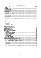
...2 3.1 External Construction ...2 3.2 Installation ...4 4. DISC SPECIFICATION ...5 4.1 STANDARDS ...9 9. FRONT INDICATOR ...9 10. DRIVE CONFIGURATION ...9 11. INTERFACE CONNECTOR ...10 ...26 14.5.1 ATA COMMAND ...26 14.5.2 ATAPI COMMAND ...27 15. POWER MANAGEMENT SPECIFICATION 29 15.1 - TEAC DW-224E-V | Hardware Specification - Page 3
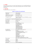
1. SCOPE This is hardware specification of the TEAC DW-224E-R93 built-in type CD-RW/DVD-ROM drive (hereinafter referred to as drive). As for the software specification, refer to "DW-224E-C Software Specification". 2. OUTLINE The outline of this drive is given in Table 2-1. (Table 2-1) Outline of the - TEAC DW-224E-V | Hardware Specification - Page 4
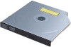
CONSTRUCTION 3.1 External Construction (1) Dimensions (a) Height : 12.7mm (excluding the front bezel) (b) Width : 128mm (excluding the front bezel) (c) Depth : 129.4mm (excluding the eject button) (2) Mass : 178g or less (3) Disc clamp system : Ball clamp (4) Loading : Manual loading - TEAC DW-224E-V | Hardware Specification - Page 5
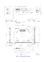
(Fig. 3.1-1) External view of the drive - 3 - ( ± 0.4 ) (Unit : mm) - TEAC DW-224E-V | Hardware Specification - Page 6
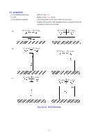
less 30° or less 30° or less 30° or less (c) 30° or less 0° or less 30° or less 30° or less (Fig. 3.2-1) Tilt of the drive - 4 - - TEAC DW-224E-V | Hardware Specification - Page 7
4. DISC SPECIFICATION 4.1 Applicable Disc Format • CD-DA • CD-ROM Mode 1 • CD-ROM XA Mode 2 (Form 1, Form 2) • Multi-session Photo CD • CD-I • Video CD • Enhanced CD • CD-TEXT • - TEAC DW-224E-V | Hardware Specification - Page 8
as the recordable disc to be used in this drive is a 79-minute disc for 8x speed manufactured by Taiyo Yuden Co., Ltd. (TEAC Part No.: T0006613, CD-R80-BULK). The use of other recordable discs is conditional on mutual understanding between TEAC and specific users. With the recommended type of discs - TEAC DW-224E-V | Hardware Specification - Page 9
: 2MB 5.2 Audio (1) Line output The following specifications apply during audio play. (a) Number of channels : 2 channels (stereo) (b) Frequency Muting : each channel independent (using the ATAPI command) (i) Volume : Software volume using the ATAPI command; 255 steps from volume level 0 to - TEAC DW-224E-V | Hardware Specification - Page 10
as specified here do not include the environmental conditions of the disc. The environmental conditions of the disc should follow the specifications of the applicable disc. (1) Ambient temperature (a) During operation : 5 to 45°C (Surface temperature on the top cover; 5 to 50°C) (b) During non - TEAC DW-224E-V | Hardware Specification - Page 11
the disc occurs, flashing continues until the disc is ejected. If an error which seems to rest with the drive's hardware, flashing continues until the power is switched OFF. 10. DRIVE CONFIGURATION The setting to master or slave is determined by the −CSEL signal (interface connector 47 pin). If - TEAC DW-224E-V | Hardware Specification - Page 12
11. INTERFACE CONNECTOR (1) Connector on the drive : JAE KX15-50KLDLE or equivalent (2) Applicable connector on the 31 DA1 32 -PDIAG (-CBLID) 33 DA0 34 DA2 35 -CS0 36 -CS1 37 -DASP 38 +5V 39 +5V 40 +5V 41 +5V 42 +5V 43 GROUND 44 GROUND 45 GROUND 46 GROUND 47 - TEAC DW-224E-V | Hardware Specification - Page 13
unbalanced) (3) AGND : Ground of audio line output. For the electrical specification of the line output, refer to 5.2. 13. POWER INTERFACE The following specifications apply to the interface connector terminals of the drive. The power should be supplied from a power supply unit with reinforced - TEAC DW-224E-V | Hardware Specification - Page 14
14.1 Outline (1) Applicable standard ANSI standard SFFC : X3T13/1321D (ATA-5) : SFF-8020i Rev. 2.6 and SFF-8090v3 14.2 Electrical Characteristics The following specifications apply to the interface connector terminal for the IDE signal of the drive. The input signals refer to the signals input to - TEAC DW-224E-V | Hardware Specification - Page 15
Table 14.3-1. Among the following signals, the input signal refers to the signal input to the CD-RW drive and the output signal refers to the signal output from the CD-RW drive and the input/output signal refers to the bidirectional signal. (Table 14.3-1) IDE Interface signal summary (Sheet 1 of - TEAC DW-224E-V | Hardware Specification - Page 16
Device address bit 1 Device address bit 2 DMA acknowledge DMA request Interupt request Drive 16 bit I/O Direction IN IN IN IN OUT OUT OUT -IOR I/O 14.4 Interface Timing The following specifications all apply to the signal interface connector terminal of the CD-ROM drive. In timing description, H - TEAC DW-224E-V | Hardware Specification - Page 17
-RESET H L t1 -DASP H L -PDIAG H L Symbol Item t1 -HRST pulse width Min Typ Max Unit 25 µs (Fig. 14.4-1) Reset timing (master) -RESET H L -DASP H L -PDIAG H L t2 t4 Symbol Item t2 -DASP assert time t4 -PDIAG assert start Min Typ Max Unit 70 400 ms 0.2 30 s (Fig. 14.4-2) - TEAC DW-224E-V | Hardware Specification - Page 18
-CS0, CS1 H DA0 ~ DA2 L -DIOW H L IORDY H L DD0 ~ DD15 H L t5 t9 t6 t10 t11 t7 t8 t14 t12 Symbol Item t5 Address setup time t6 -IOW pulse width t7 Address hold time t8 -IOW interactive pulse width t9 IORDY delay time t10 IORDY pulse width t11 Write data setup time t12 Write - TEAC DW-224E-V | Hardware Specification - Page 19
-CS0, CS1 H DA0 ~ DA2 L -DIOR H L IORDY H L DD0 ~ DD15 H L t15 t16 t19 t20 t17 t18 t24 t22 Symbol Item t15 Address setup time t16 -DIOR pulse width t17 Address hold time t18 -DIOR interactive pulse width t19 IORDY delay time t20 IORDY pulse width t22 Read data hold time t24 - TEAC DW-224E-V | Hardware Specification - Page 20
DMARQ H L -DMACK H L -DIOW H L DD0 ~ DD15 H L -DIOR H L DD0 ~ DD15 H L t26 t34 t36 t27 t28 t30 t31 t32 t33 Symbol Item Min Max Unit t26 From -DMACK assert to -DMAREQ negate 80 ns t27 From -DMACK assert to -DIOW low 0 ns t28 -DIOW, -DIOR pulse width 120 ns t30 Write - TEAC DW-224E-V | Hardware Specification - Page 21
DMARQ H L -DMACK H L -DIOW H L DD0 ~ DD15 H L -DIOR H L DD0 ~ DD15 H L t45 t38 t39 t48 t40 t46 t41 t42 t43 t44 t49 Symbol Item Min Max Unit t38 From -DMACK assert to -DIOW low 0 ns t39 -DIOW, -DIOR pulse width 70 ns t40 -DIOW, -DIOR interactive pulse width 25 ns t41 - TEAC DW-224E-V | Hardware Specification - Page 22
Initiating an Ultra DMA data in burst DMARQ H (device) L -DMACK H (host) L STOP H (host) L t50 t51 t52 −HDMARDY H (host) L DSTROBE H (device) L DD(15:0) H (device) L DA0, DA1, DA2 H (host) L −CS0, −CS1 H (host) L t51 t52 t54 t55 t51 t51 Sustained Ultra DMA data in - TEAC DW-224E-V | Hardware Specification - Page 23
Device terminating an Ultra DMA data in burst DMARQ H (device) L -DMACK H (host) L t64 t64 STOP H (host) L t64 −HDMARDY H (host) L t66 DSTROBE H (device) L t67 t55 DD(15:0) H (device) L DA0, DA1, DA2 H (host) L −CS0, −CS1 H (host) L Host terminating an Ultra DMA - TEAC DW-224E-V | Hardware Specification - Page 24
time (STOP/-HDMARDY 0 ↓ to DSTROBE ↓ ) 170 ns t54 DSTROBE drive delay time (to -DMACK ↓) 0 ns t55 Output data, release delay time (to -DMACK ↓) 10 ns t56 Output data, drive start time (to STOP ↓/ 0 ns -HDMARDY ↓) t57 Valid data, setup - TEAC DW-224E-V | Hardware Specification - Page 25
Initiating an Ultra DMA data out burst DMARQ H (device) L -DMACK H (host) L STOP H (host) L −DDMARDY H (device) L HSTROBE H (host) L DD(15:0) H (host) L DA0, DA1, DA2 H (host) L −CS0, −CS1 H (host) L Sustained Ultra DMA data out burst t70 t71 t72 t73 t71 t71 t71 - TEAC DW-224E-V | Hardware Specification - Page 26
Host terminating an Ultra DMA data out burst t74 DMARQ H (device) L t74 -DMACK H (host) L t83 STOP H (host) L t74 −DDMARDY H (device) L HSTROBE H (host) L DD(15:0) H (host) L DA0, DA1, DA2 H (host) L −CS0, −CS1 H (host) L Device terminating an Ultra DMA data t81 t71 - TEAC DW-224E-V | Hardware Specification - Page 27
Unlimited interlock time 0 ns t71 Setup time/Hold time (to -DMACK ↓ ) 20 ns t72 Envelope time(-DMACK ↓ to STOP ↓) 20 70 ns t73 -DDMARDY drive delay time (to -DMACK ↓) 0 ns t74 Limited interlock time 0 150 ns t75 Data setup time (to -HSTROBE edge/to 7 ns -DMACK ↑) t76 Data hold - TEAC DW-224E-V | Hardware Specification - Page 28
.5.1 ATA COMMAND Refer to table 14.5.1-1. (Table 14.5.1-1) ATA COMMAND CODE 08 E5 90 E3 E1 00 A0 A1 EF E6 E2 E0 A2 COMMAND ATAPI SOFT RESET CHECK POWER MODE EXECUTE DRIVE DIAGNOSTIC IDLE IDLE IMMEDIATE NOP ATAPI PKT. ATAPI IDENTIFY DEVICE SET FEATURE SLEEP STANDBY STANDBY IMMEDIATE SERVICE - 26 - TEAC DW-224E-V | Hardware Specification - Page 29
2) CODE A1 5B 04 4A 12 BD 55 5A 4B 45 A5 47 49 A9 1E 28 A8 5C 25 BE B9 51 44 42 43 52 03 53 01 BA 2B 5D 54 BB 1B 4E 35 COMMAND BLANK CLOSE TRACK/SESSION FORMAT UNIT GET EVENT STATUS NOTIFICATION INQUIRY MECHANISM - TEAC DW-224E-V | Hardware Specification - Page 30
(Table 14.5.2-1) List of the ATAPI commands (Sheet 2 of 2) CODE 00 2A AA AD 23 A4 A3 A7 46 AC A2 COMMAND TEST UNIT READY WRITE (10) WRITE (12) READ DVD STRUCTURE READ FORMATTED CAPACITIES REPORT KEY SEND KEY SET READ AHEAD GET CONFIGURATION GET PERFORMANCE SEND EVENT - 28 - - TEAC DW-224E-V | Hardware Specification - Page 31
15. POWER MANAGEMENT SPECIFICATION This drive has a power management function to reduce power consumption. 15.1 Power Management Modes The drive has the following four power management modes. The transition between these modes is performed by the timer within the drive or a command issued by the - TEAC DW-224E-V | Hardware Specification - Page 32
the sleep mode is initiated using the SRST or the ATAPI SOFT RESET command, the drive enters the standby mode. (9) Tray ejection in each of the active, idle, If the tray is ejected in the active, idle or standby mode, the drive enters the standby mode when the tray is out or the sleep mode when the - TEAC DW-224E-V | Hardware Specification - Page 33
enter the standby mode. 15.5 Sleep Mode The drive enters a state in which all functions are stopped and no command can be received. The transition to the sleep mode is possible using the SLEEP command. For details, refer to the Software Specification. The resumption from the sleep mode is possible - TEAC DW-224E-V | Hardware Specification - Page 34
unit or a system with this unit to an end user, print the following text in the instruction manual or enclose the separate sheet on which the following text is printed with the instruction manual. This product has been designed and manufactured according to FDA regulations "title 21. CFR. chapter1
-
 1
1 -
 2
2 -
 3
3 -
 4
4 -
 5
5 -
 6
6 -
 7
7 -
8
-
9
-
10
-
11
-
12
-
13
-
14
-
15
-
16
-
17
-
18
-
19
-
20
-
21
-
22
-
23
-
24
-
25
-
26
-
27
-
28
-
29
-
30
-
31
-
32
-
33
-
34
 |
 |

34 sheets in Total
TEAC DW-224E-R93
CD-RW/DVD-ROM DRIVE
HARDWARE SPECIFICATION
Rev. A
7757a