TEAC DW-224E-V Hardware Specification - Page 11
Reliability, Safety Standards, Front Indicator, Drive Configuration
 |
View all TEAC DW-224E-V manuals
Add to My Manuals
Save this manual to your list of manuals |
Page 11 highlights
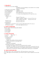
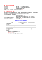
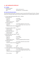
7. RELIABILITY (1) Mean time between failures (MTBF) : 60,000POH or more (the frequency of use should be 10% at normal temperature and humidity) (2) Mean time to repair (MTTR) : 30minutes (3) Loading/ejecting life : 10,000times or more (4) Power ON/OFF life : 60,000 times or more (5) Laser diode life : MTTF 9,000 hours (Duty 50% pulse 83mW, 60°C) (6) Seeking life : 2 × 10⁶ times or more (random access, 25°C, duty; 20% or less) (7) Error rate (a) Read error rate DVD : Once per 1012 bits or less CD : MODE 1 and MODE 2 (FORM 1) : Once per 1012 bits or less MODE 2 (FORM 2) and CDDA : Once per 109 bits or less (b) Seek error rate : Once per 106 seeks or less (c) Seek error rate : Once per 106 seeks or less (8) Self-diagnosis (a) When power is switched ON: Various controllers, ROM, RAM, buffer, ECC circuit, etc. (b) When disc is inserted : Servo circuit, signal processors, etc. 8. SAFETY STANDARDS The drive complies with the following safety standards: (1) UL standard (2) CSA standard (3) TÜV standard (4) CE standard 9. FRONT INDICATOR (1) Location : Refer to Fig. 3.1-1. (2) Color : Green (3) Lighting conditions (a) Continuous on • During seek • Transfer of the read data to the host is under way. (b) Flashing with a period of 3 second (Duty 50%) • During write • While audio is being played (c) Flashing with a period of 1 second (Duty 50%) • From POR or tray loading to the end of TOC read (when the disc is present) • From POR or tray loading to the end of detecting the disc (when the disc is not present). If an error which is considered to arise from the disc occurs, flashing continues until the disc is ejected. If an error which seems to rest with the drive's hardware, flashing continues until the power is switched OFF. 10. DRIVE CONFIGURATION The setting to master or slave is determined by the −CSEL signal (interface connector 47 pin). If the −CSEL signal is at low level, the drive is set to the slave, and if it is open or at high level, it is set to the master. - 9 -
-
 1
1 -
2
-
3
-
4
-
5
-
 6
6 -
 7
7 -
 8
8 -
 9
9 -
 10
10 -
 11
11 -
 12
12 -
 13
13 -
 14
14 -
 15
15 -
 16
16 -
17
-
18
-
19
-
20
-
21
-
22
-
23
-
24
-
25
-
26
-
27
-
28
-
29
-
30
-
31
-
32
-
33
-
34
 |
 |
