TEAC DW-224E-V Hardware Specification - Page 6
Installation
 |
View all TEAC DW-224E-V manuals
Add to My Manuals
Save this manual to your list of manuals |
Page 6 highlights
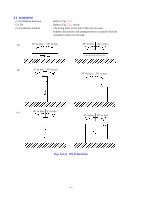
3.2 Installation (1) Installation direction (2) Tilt (3) Installation method : Refer to Fig. 3.2-1 : Refer to Fig. 3.2-1 below. : The fixing holes in the side of the unit are used. Separate discussions and arrangements are required when the installation holes are not used. (a) 30° or less 30° or less 30° or less 30° or less (b) 0° or less 30° or less 30° or less 30° or less (c) 30° or less 0° or less 30° or less 30° or less (Fig. 3.2-1) Tilt of the drive - 4 -
-
 1
1 -
 2
2 -
 3
3 -
 4
4 -
 5
5 -
 6
6 -
 7
7 -
 8
8 -
 9
9 -
 10
10 -
 11
11 -
 12
12 -
13
-
14
-
15
-
16
-
17
-
18
-
19
-
20
-
21
-
22
-
23
-
24
-
25
-
26
-
27
-
28
-
29
-
30
-
31
-
32
-
33
-
34
 |
 |

° 4 °
3.2
Installation
(1) Installation direction
: Refer to Fig.
3.2-1
(2) Tilt
: Refer to Fig.
3.2-1
below.
(3) Installation method
: The fixing holes in the side of the unit are used.
Separate discussions and arrangements are required when the
installation holes are not used.
(Fig. 3.2-1)
Tilt of the drive
30² or less
30² or less
30² or less
30² or less
30² or less
30² or less
0² or less
30² or less
30² or less
30² or less
30² or less
0² or less
(a)
(b)
(c)