TEAC DW-224E-V Hardware Specification - Page 18
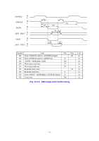
Fig. 14.4-3, PIO write cycle timing
 |
View all TEAC DW-224E-V manuals
Add to My Manuals
Save this manual to your list of manuals |
Page 18 highlights
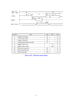
-CS0, CS1 H DA0 ~ DA2 L -DIOW H L IORDY H L DD0 ~ DD15 H L t5 t9 t6 t10 t11 t7 t8 t14 t12 Symbol Item t5 Address setup time t6 -IOW pulse width t7 Address hold time t8 -IOW interactive pulse width t9 IORDY delay time t10 IORDY pulse width t11 Write data setup time t12 Write data hold time t14 Write cycle time Min Max Unit 25 ns 70 ns 10 ns 25 ns 35 ns 1,250 ns 20 ns 10 ns 120 ns (Fig. 14.4-3) PIO write cycle timing - 16 -
-
 1
1 -
2
-
3
-
4
-
5
-
6
-
7
-
8
-
9
-
10
-
11
-
12
-
 13
13 -
 14
14 -
 15
15 -
 16
16 -
 17
17 -
 18
18 -
 19
19 -
 20
20 -
 21
21 -
 22
22 -
 23
23 -
24
-
25
-
26
-
27
-
28
-
29
-
30
-
31
-
32
-
33
-
34
 |
 |

° 16 °
(Fig. 14.4-3)
PIO write cycle timing
Symbol
Item
Min
Max
Unit
t5
Address setup time
25
ns
t6
°IOW pulse width
70
ns
t7
Address hold time
10
ns
t8
°IOW interactive pulse width
25
ns
t9
IORDY delay time
35
ns
t10
IORDY pulse width
1,250
ns
t11
Write data setup time
20
ns
t12
Write data hold time
10
ns
t14
Write cycle time
120
ns
H
L
H
L
H
L
H
L
°CS0, CS1
DA0 ~ DA2
°DIOW
IORDY
DD0 ~ DD15
t5
t6
t7
t8
t9
t10
t11
t12
t14