Weider 9900i Uk Manual - Page 23
x 50mm Button Bolt 76, two Half Guards 72
 |
View all Weider 9900i manuals
Add to My Manuals
Save this manual to your list of manuals |
Page 23 highlights
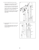
39. Route the Low Cable (43) under a Pulley (69). 39 Attach the Pulley (69) and a Cable Trap (71) to the center bracket on the Base (1) with an M10 x 50mm Button Bolt (76), two Half Guards (72), and an M10 Locknut (74). Make sure that the Cable Trap (71) is oriented to hold the Low Cable (43) in the groove of the Pulley (69). Make sure that the Half Guards (72) are outside the bracket. 40. Route the Low Cable (43) over a Pulley (69). 40 Using the last hole in the Pulley Plates (70), attach the Pulley Plates to the Pulley (69) with an M10 x 43mm Bolt (65) and an M10 Locknut (74). 69 74 43 72 71 72 1 76 74 70 65 69 43 41. Route the Low Cable (43) under a Pulley (69). 41 Attach the Pulley (69) and a Cable Trap (71) to the rear bracket on the Base (1) with an M10 x 50mm Button Bolt (76), two Half Guards (72), and an M10 Locknut (74). Make sure that the Cable Trap (71) is oriented to hold the Low Cable (43) in the groove of the Pulley (69). Make sure that the Half Guards (72) are outside the bracket. 69 43 74 72 71 1 72 76 23
-
 1
1 -
2
-
3
-
4
-
5
-
6
-
7
-
8
-
9
-
10
-
11
-
12
-
13
-
14
-
15
-
16
-
17
-
 18
18 -
 19
19 -
 20
20 -
 21
21 -
 22
22 -
 23
23 -
 24
24 -
 25
25 -
 26
26 -
 27
27 -
 28
28 -
29
-
30
-
31
-
32
-
33
-
34
-
35
-
36
-
37
-
38
-
39
-
40
-
41
-
42
-
43
-
44
-
45
-
46
-
47
-
48
 |
 |
