Whirlpool GBS277PDB Technical Guide - Page 49
Control Panel Test Locations, Relay Logic Chart
 |
View all Whirlpool GBS277PDB manuals
Add to My Manuals
Save this manual to your list of manuals |
Page 49 highlights
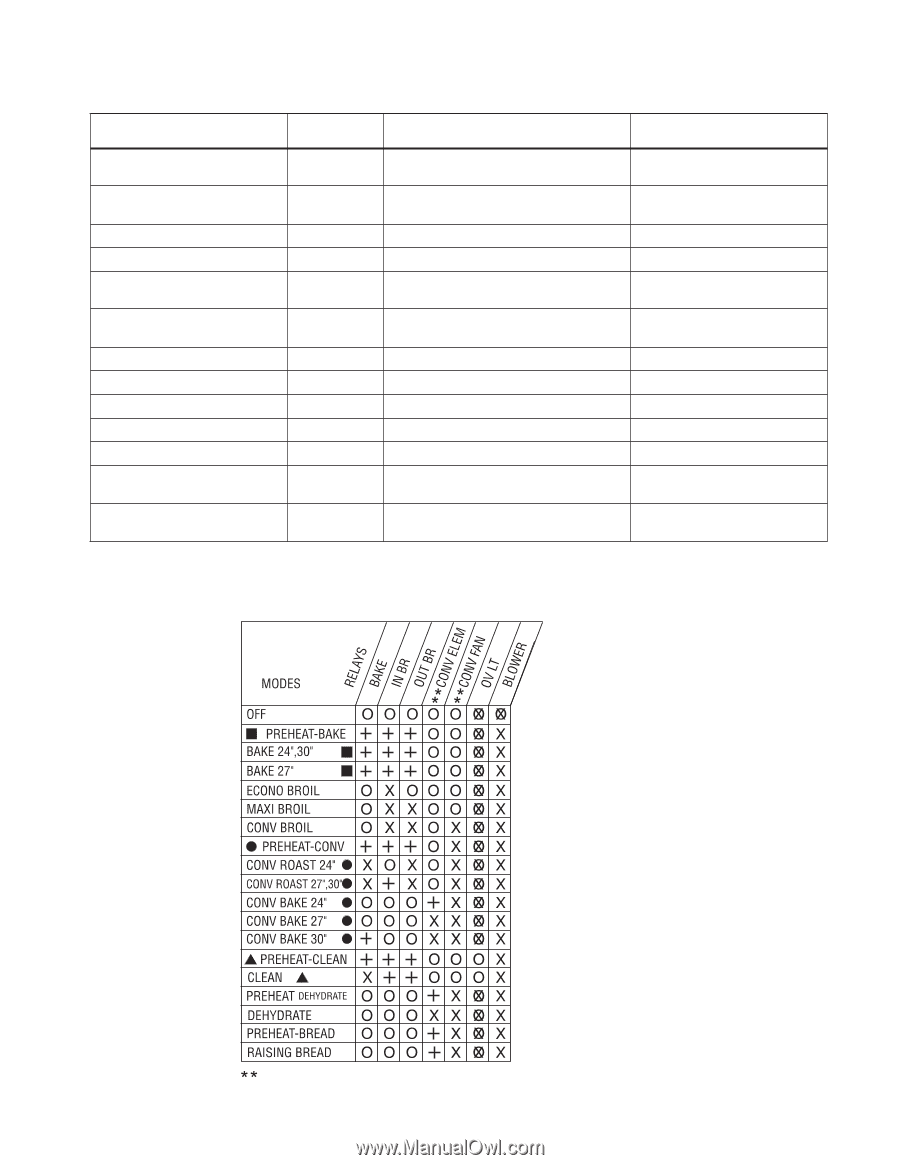
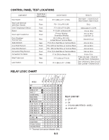
CONTROL PANEL TEST LOCATIONS COMPONENT Door Switch Door Lock Solenoid (with Door Closed) Oven Temperature Sensor Blower Oven Light Transformer Oven Shutdown Thermal Fuse Bake Element Inner Broil Element Outer Broil Element Convection Ring Element Convection Fan Motor Meat Probe Jack Latch Switch FRONT/REAR SERVICEABLE Front CHECK POINTS P7-2 (BR) to P7-1 (TAN) RESULTS Door Open = Closed Circuit Door Closed = Open Circuit Front P6-1 (Y) to P6-2 (W) 50 Ω Front Rear Front Rear Rear Front Front Front Rear Rear Front P7-4 (V) to P7-6 (GN) P1-5 (GY) to Neutral (W) Primary Winding Secondary Winding P5-2 (OR) or P5-3 (R) to Red Wire at Terminal Block P5-3 (R) to Red Wire at Terminal Block P5-2 (OR) to Red Wire at Terminal Block P5-1 (BU) to Red Wire at Terminal Block P5-4 (Y) to Red Wire at Terminal Block P1-6 (OR) to Neutral (W) P7-7 (GN) to P7-8 (Y) P7-3 (BU) to P7-1 (TAN) 1080 Ω @ 21°C (70°F) 14 Ω to 18 Ω 40 Ω to 45 Ω Less than1 Ω Closed Circuit 25 Ω to 30 Ω 45 Ω to 55 Ω 45 Ω to 55 Ω 28 Ω to 35 Ω 8 Ω to 12 Ω Probe into Jack - Check for 78k Ω @ Room Temperature Door Unlocked = Open Circuit Door Locked = Closed Circuit RELAY LOGIC CHART RELAY LOGIC KEY O - OFF X - ON +- CYCLING (MAX PERIOD = 60SEC) OX - ON OR OFF Thermal Convection Models Only 6-3
-
 1
1 -
2
-
3
-
4
-
5
-
6
-
7
-
8
-
9
-
10
-
11
-
12
-
13
-
14
-
15
-
16
-
17
-
18
-
19
-
20
-
21
-
22
-
23
-
24
-
25
-
26
-
27
-
28
-
29
-
30
-
31
-
32
-
33
-
34
-
35
-
36
-
37
-
38
-
39
-
40
-
41
-
42
-
43
-
 44
44 -
 45
45 -
 46
46 -
 47
47 -
 48
48 -
 49
49 -
 50
50 -
 51
51 -
 52
52 -
 53
53 -
 54
54 -
55
-
56
-
57
-
58
-
59
-
60
 |
 |