Yamaha CLP-S308PE Owners Manual - Page 85
While pushing the lower part of D and E from, outside, secure the bottom end of B using four
 |
View all Yamaha CLP-S308PE manuals
Add to My Manuals
Save this manual to your list of manuals |
Page 85 highlights
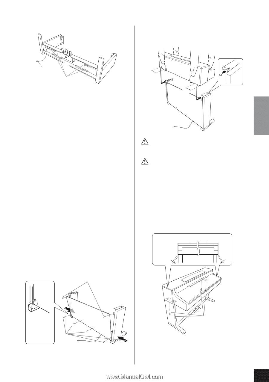
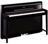
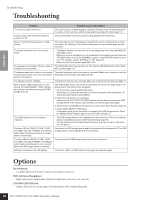
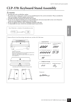
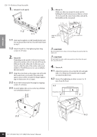
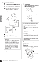
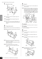
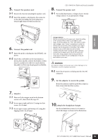
ENGLISH 1. Attach C to D and E. D CLP-340/330: Keyboard Stand Assembly 3. Mount A. Be sure to place your hands at least 15 cm from either end of the main unit when positioning it. C E 1-1 1-2 1-1 Untie and straighten out the bundled pedal cord. Do not discard the vinyl tie. You will need it later in step 5. 1-2 Attach D and E to C by tightening four long screws (6 x 25 mm). 15 cm or further in A 15 cm or further in 2. Attach B. Depending on the model of Clavinova you purchased, the surface color of one side of B may be different from the other side. In this case, position B so that the side of the surface color most similar to D and E faces you (as you would play the instrument). 2-1 Place the lower side of B on each foot of D and E, then align the screw holes on the upper side of B with the bracket holes on D and E. 2-2 Attach the top corners of B to D and E by finger- tightening two thin screws (4 x 12 mm). 2-3 While pushing the lower part of D and E from outside, secure the bottom end of B using four tapping screws (4 x 20 mm). 2-4 Securely tighten the screws on the top of B that were attached in Step 2-2. 2-2 2-4 2-1 E CAUTION Be extra careful not to drop or let your fingers be pinched by the main unit. CAUTION Do not hold the main unit in any position other than the position specified above. 4. Secure A. 4-1 Adjust the position of A so that the left and right ends of A will project beyond D and E equally (as seen from the front). 4-2 Secure A by tightening the short screws (6 x 16 mm) from the front. 4-1 A Projection of A Place the bottom end of the B D rear panel on each foot. 2-3 4-2 Insert the screw in the front of these two holes. CLP-370/340/330, CLP-S308/S306 Owner's Manual 85
-
 1
1 -
2
-
3
-
4
-
5
-
6
-
7
-
8
-
9
-
10
-
11
-
12
-
13
-
14
-
15
-
16
-
17
-
18
-
19
-
20
-
21
-
22
-
23
-
24
-
25
-
26
-
27
-
28
-
29
-
30
-
31
-
32
-
33
-
34
-
35
-
36
-
37
-
38
-
39
-
40
-
41
-
42
-
43
-
44
-
45
-
46
-
47
-
48
-
49
-
50
-
51
-
52
-
53
-
54
-
55
-
56
-
57
-
58
-
59
-
60
-
61
-
62
-
63
-
64
-
65
-
66
-
67
-
68
-
69
-
70
-
71
-
72
-
73
-
74
-
75
-
76
-
77
-
78
-
79
-
 80
80 -
 81
81 -
 82
82 -
 83
83 -
 84
84 -
 85
85 -
 86
86 -
 87
87 -
 88
88 -
 89
89 -
 90
90 -
91
-
92
-
93
-
94
-
95
-
96
-
97
-
98
-
99
-
100
-
101
-
102
-
103
-
104
-
105
-
106
-
107
-
108
 |
 |