Yamaha CLP-S308PE Owners Manual - Page 89
Connect the speaker cord., Attach C., Set the adjuster to secure the pedals.
 |
View all Yamaha CLP-S308PE manuals
Add to My Manuals
Save this manual to your list of manuals |
Page 89 highlights
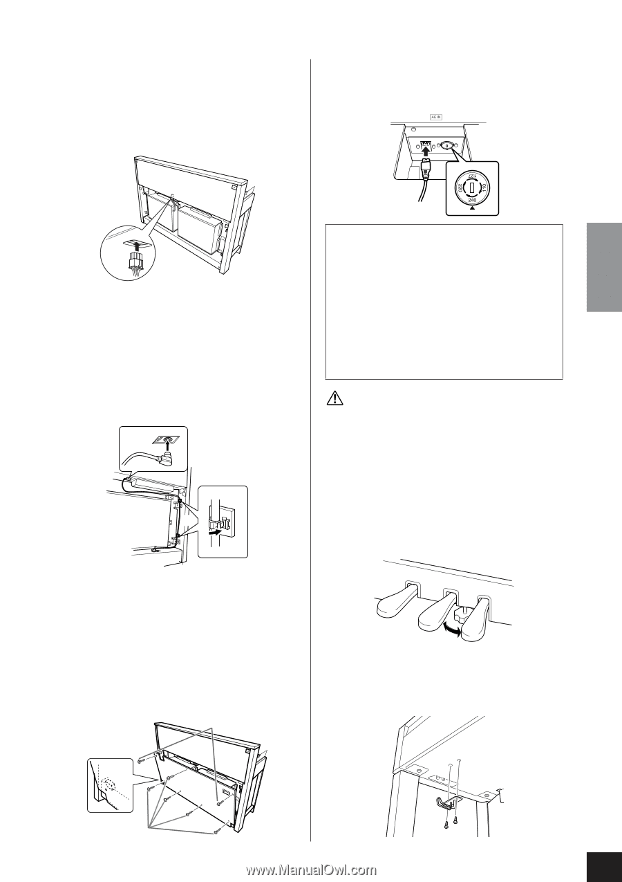
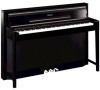
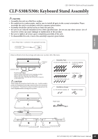
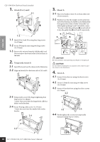
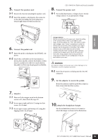
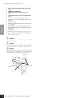
5. Connect the speaker cord. 5-1 Remove the twist tie attaching the speaker cord. 5-2 Insert the speaker cord plug into the connector so that the protruding tab on the plug faces toward right when viewed from the rear. CLP-S308/S306: Keyboard Stand Assembly 8. Connect the power cord. 8-1 For models that feature a voltage selector: Set the voltage selector to an appropriate voltage. ENGLISH 5-2 6. Connect the pedal cord. 6-1 Insert the pedal cord plug into the [PEDAL] con- nector. 6-2 Attach the cord holders to the instrument as shown, then clip the cord into the holders. At this time, be careful not to allow too much slack in the pedal cord between the plug and cord holder. 6-1 6-2 E Voltage Selector Before connecting the AC power cord, check the setting of the voltage selector which is provided in some areas. To set the selector for 110V, 127V, 220V or 240V main voltages, use a "minus" screwdriver to rotate the selector dial so that the correct voltage for your region appears next to the pointer on the panel. The voltage selector is set at 240V when the unit is initially shipped. After the proper voltage has been selected, connect the AC power cord to the AC IN and an AC wall outlet. A plug adaptor may be also provided in some areas to match the pin configuration of the AC wall outlets in your area. WARNING An improper voltage setting can cause serious damage to the Clavinova or result in improper operation. 8-2 Insert the AC power cord plug into the [AC IN] connector. 9. Set the adjuster to secure the pedals. Rotate the adjuster until the pedal box comes in firm contact with the floor surface. 7. Attach C. 7-1 Place on D, the stopper-wood in the bottom corners of C, then attach the top of C. 7-2 Secure upper right and left of C using two thin screws (4 x 14 mm). 7-3 Secure upper center and bottom of C using five tapping screws (4 x 20 mm). 7-2 10.Attach the headphone hanger. Use the included two screws (4 x 10 mm) to attach the hanger as shown in the illustration. 7-1 D C C 7-3 CLP-370/340/330, CLP-S308/S306 Owner's Manual 89
-
 1
1 -
2
-
3
-
4
-
5
-
6
-
7
-
8
-
9
-
10
-
11
-
12
-
13
-
14
-
15
-
16
-
17
-
18
-
19
-
20
-
21
-
22
-
23
-
24
-
25
-
26
-
27
-
28
-
29
-
30
-
31
-
32
-
33
-
34
-
35
-
36
-
37
-
38
-
39
-
40
-
41
-
42
-
43
-
44
-
45
-
46
-
47
-
48
-
49
-
50
-
51
-
52
-
53
-
54
-
55
-
56
-
57
-
58
-
59
-
60
-
61
-
62
-
63
-
64
-
65
-
66
-
67
-
68
-
69
-
70
-
71
-
72
-
73
-
74
-
75
-
76
-
77
-
78
-
79
-
80
-
81
-
82
-
83
-
 84
84 -
 85
85 -
 86
86 -
 87
87 -
 88
88 -
 89
89 -
 90
90 -
 91
91 -
 92
92 -
 93
93 -
 94
94 -
95
-
96
-
97
-
98
-
99
-
100
-
101
-
102
-
103
-
104
-
105
-
106
-
107
-
108
 |
 |