Yamaha CLP-S308PE Owners Manual - Page 88
Attach D to E and F., Temporarily mount B., Mount A., Secure A.
 |
View all Yamaha CLP-S308PE manuals
Add to My Manuals
Save this manual to your list of manuals |
Page 88 highlights
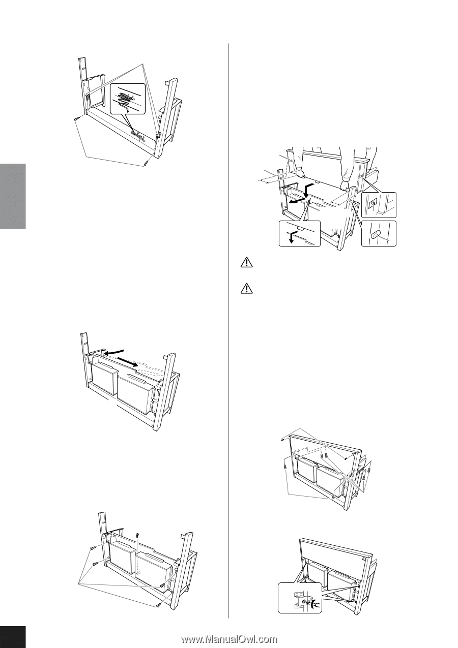
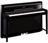
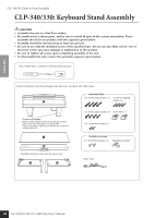
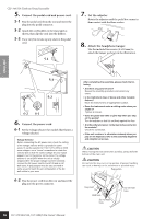
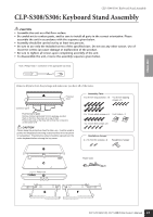
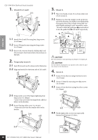
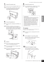
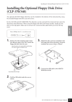
ENGLISH CLP-S308/S306: Keyboard Stand Assembly 1. Attach D to E and F. 1-1 F 1-3 E D 1-2 1-1 Attach D to E and F by using four long screws (6 x 20 mm). 1-2 Secure D from the rear using two long screws (6 x 20 mm). 1-3 Remove the twist tie from the folded pedal cord. Do not remove the twist tie that is located next to the hole. 2. Temporarily mount B. 2-1 Insert B between E and F as shown in the illustration. 2-2 Align and attach B to the front side of D, E and F. 2-1 2-2 F B E D 2-3 Temporarily secure B by finger-tightening four long screws (6 x 20mm). * Insert four screws into the larger holes (all four holes) on the brackets. 2-4 Secure B using a thin screw (4 x 14 mm). * Insert the screw into the smaller hole on the bracket. 2-4 3. Mount A. 3-1 Place your hands at least 15 cm from either end of A to mount it. 3-2 Position A so that the stopper-wood on the rear side of the bottom of A will be located behind the front panel, then slide A slowly toward the rear while lightly pushing E and F toward the center. * Be sure to slide the guide pins 1 on each side of A into the guide slots 2 on E and F respectively. 1 2 A 15cm or 3-1 further in F 3-2 15cm or E 1 further in 2 CAUTION Be extra careful to avoid pinching your fingers or dropping A. CAUTION Do not hold the keyboard in any position other than the position shown in the illustration. 4. Secure A. 4-1 Secure A from the rear using two short screws (6 x 16 mm). 4-2 Secure A from the rear using two thin screws (4 x 14 mm). 4-3 Secure A from the front using four short screws (6 x 16mm). 4-2 A 4-1 4-3 4-4 Firmly tighten the screws you temporarily fastened on B in steps 2-3 above. 2-3 4-4 88 CLP-370/340/330, CLP-S308/S306 Owner's Manual
-
 1
1 -
2
-
3
-
4
-
5
-
6
-
7
-
8
-
9
-
10
-
11
-
12
-
13
-
14
-
15
-
16
-
17
-
18
-
19
-
20
-
21
-
22
-
23
-
24
-
25
-
26
-
27
-
28
-
29
-
30
-
31
-
32
-
33
-
34
-
35
-
36
-
37
-
38
-
39
-
40
-
41
-
42
-
43
-
44
-
45
-
46
-
47
-
48
-
49
-
50
-
51
-
52
-
53
-
54
-
55
-
56
-
57
-
58
-
59
-
60
-
61
-
62
-
63
-
64
-
65
-
66
-
67
-
68
-
69
-
70
-
71
-
72
-
73
-
74
-
75
-
76
-
77
-
78
-
79
-
80
-
81
-
82
-
 83
83 -
 84
84 -
 85
85 -
 86
86 -
 87
87 -
 88
88 -
 89
89 -
 90
90 -
 91
91 -
 92
92 -
 93
93 -
94
-
95
-
96
-
97
-
98
-
99
-
100
-
101
-
102
-
103
-
104
-
105
-
106
-
107
-
108
 |
 |