Yamaha HTR-5590 Owner's Manual
Yamaha HTR-5590 Manual
 |
View all Yamaha HTR-5590 manuals
Add to My Manuals
Save this manual to your list of manuals |
Yamaha HTR-5590 manual content summary:
- Yamaha HTR-5590 | Owner's Manual - Page 1
U HTR-5590 AV Receiver OWNER'S MANUAL IMPORTANT Please record the serial number of this unit in the space below. MODEL: Serial No.: The serial number is located on the rear of the unit. Retain this Owner's Manual in a safe place for future reference. - Yamaha HTR-5590 | Owner's Manual - Page 2
IMPORTANT SAFETY INSTRUCTIONS CAUTION RISK OF ELECTRIC SHOCK DO NOT OPEN CAUTION: TO REDUCE THE RISK OF ELECTRIC SHOCK, DO NOT REMOVE COVER (OR BACK). NO USER-SERVICEABLE PARTS INSIDE. REFER SERVICING TO QUALIFIED SERVICE PERSONNEL. • Explanation of Graphical Symbols The lightning flash with - Yamaha HTR-5590 | Owner's Manual - Page 3
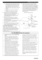
810-21) GROUND CLAMPS POWER SERVICE GROUNDING ELECTRODE SYSTEM (NEC ART 250. PART H) FCC INFORMATION (for US customers) 1. IMPORTANT NOTICE : DO NOT MODIFY THIS UNIT! This product, when installed as indicated in the instructions contained in this manual, meets FCC requirements. Modifications - Yamaha HTR-5590 | Owner's Manual - Page 4
qualified YAMAHA service personnel when any service is needed. The cabinet should never be opened for any reasons. 15 When not planning to use this unit for long periods of time (i.e. vacation), disconnect the AC power plug from the wall outlet. 16 Be sure to read the "TROUBLESHOOTING" section - Yamaha HTR-5590 | Owner's Manual - Page 5
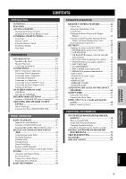
and Australia models 68 Remote Control in Zone 2 69 ADDITIONAL INFORMATION SOUND FIELD PROGRAM PARAMETER EDITING 70 What is a Sound Field 70 Sound Field Program Parameters 70 Changing Parameter Settings 71 Resetting a Parameter to the Factory-set Value ....... 71 DIGITAL SOUND FIELD PARAMETER - Yamaha HTR-5590 | Owner's Manual - Page 6
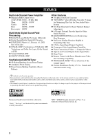
Display Function Helpful in Controlling This Unit N S Video Signal Input/Output Capability N Component Video Input/Output Capability N Video Conversion (S Video → Composite Video) N Optical and Coaxial Digital Audio Signal Jacks N Sleep Timer N Remote Control with Preset Manufacturer Codes and - Yamaha HTR-5590 | Owner's Manual - Page 7
SUR. 10 0 SELECT 11 +10 EX/ES 12 CHP/INDEX Indoor FM antenna (For U.S.A., Canada and China models) AM loop antenna (For Australia model) Installing Batteries in the Remote Control 2 1 3 1 Press the part and slide the battery compartment cover off. 2 Insert four supplied batteries (AAA, R03, UM - Yamaha HTR-5590 | Owner's Manual - Page 8
CONTROLS AND FUNCTIONS Front Panel 12 3 4 5 6 7 NATURAL SOUND AV RECEIVER D I G I TA L STANDBY /ON 6CH INPUT MODE SPEAKERS A B BASS PROCESSOR EXTENSION DIRECT TUNER DSP A/B/C/D/E PRESET/ TUNING STEREO EFFECT PROGRAM PRESET TUNING /TUNING FM/AM MEMORY MODE EDIT PHONES MAN'L/ - Yamaha HTR-5590 | Owner's Manual - Page 9
Opening and closing the front panel door When you want to use the controls behind the front panel door, open the door by gently pressing on the lower part of the panel. When you are not using them, close the door. NATURAL SOUND AV RECEIVER HTR-5990 D I G I TA L To open, press gently on the lower - Yamaha HTR-5590 | Owner's Manual - Page 10
source (see page 54). 6 Input selector buttons Select the input source and change the control area (see "REMOTE CONTROL FEATURES" on pages 44 to 54). 7 Display window Shows the selected source component that you are controlling. 8 TV POWER Turns on and off the power of the TV. 9 Operation Section - Yamaha HTR-5590 | Owner's Manual - Page 11
speakers without effect sounds. All Dolby Digital and DTS audio signals except for the LFE channel are also directed to the main left and right speakers. CONTROLS AND FUNCTIONS Using the Remote Control NATURAL SOUND AV RECEIVER D I G I TA L STANDBY /ON 6CH INPUT MODE SPEAKERS A B BASS - Yamaha HTR-5590 | Owner's Manual - Page 12
/ SP AB DTS Neo:6 DOLBY DIGITAL PRO LOGIC MOVIE TV THEATER 12 ENTERTAINMENT TUNER CD STEREO AUTO TUNED MEMORY PHONO MUTE SLEEP BASS P. DIRECT ft mS dB VOLUME LFE L CR RL RC RR 0 qwe r ty u i o pa 1 DSP indicator Lights up when you select a digital sound field program. 2 Decoder indicators - Yamaha HTR-5590 | Owner's Manual - Page 13
output to your speaker impedance (see page 13). Set this unit in the standby mode before you change the setting of this switch. 6 AC power cord Connect to a power outlet. 7 AC OUTLETS Use these outlets to supply power to your other A/V components (see page 21). 8 DIGITAL INPUT jacks < China model - Yamaha HTR-5590 | Owner's Manual - Page 14
, but also for reproducing the LFE (low-frequency effect) channel with high fidelity when the Dolby Digital signal or the DTS signal is played back. The YAMAHA Active Servo Processing Subwoofer System is ideal for natural and lively bass reproduction. Refer to the following diagram when you place - Yamaha HTR-5590 | Owner's Manual - Page 15
the left channel (L), right channel (R), "+" (red) and "-" (black) properly. If the connections are faulty, no sound will be heard to secure the wire. Banana plug y (For U.S.A., Canada, Australia and China models) • Banana plug connections are also possible. First, tighten the knob and then - Yamaha HTR-5590 | Owner's Manual - Page 16
ANT 75Ω UNBAL. ZONE 2 OUT MONITOR OUT VIDEO S VIDEO R+ REMOTE IN OUT CONTROL OUT +12V 15mA MAX. -A - +L OUTPUT + SUB WOOFER R+ + - MAIN - B - REAR (SURROUND) - - - + +L + IMPEDANCE SELECTOR SET BEFORE POWER ON MAIN A OR B: 4ΩMIN. /SPEAKER A+B: 8ΩMIN. /SPEAKER CENTER : 6ΩMIN - Yamaha HTR-5590 | Owner's Manual - Page 17
this unit fails to turn on when STANDBY/ON (or SYSTEM POWER) is pressed, the IMPEDANCE SELECTOR switch may not be fully main speakers, the impedance of each speaker must be 16 Ω or higher. [U.S.A. and Canada models] The impedance of each speaker must be 8 Ω or higher. Center The impedance must be - Yamaha HTR-5590 | Owner's Manual - Page 18
and other components to mains power until all connections between jack names. Refer to the operation instructions for each component to be connected to owner's manual that came with the component being connected. I VIDEO AUX jacks (on the front panel) These jacks are used to connect any video input - Yamaha HTR-5590 | Owner's Manual - Page 19
COMPONENT OUTPUT VIDEO S VIDEO OUTPUT OUTPUT O LR V S VV V (U.S.A. and Canada models) DIGITAL OUTPUT OPTICAL MD/TAPE IN (PLAY) AUDIO R L CD-R MD/TAPE OUT (REC) CD CD-R IN (PLAY) CD-R OUT (REC) DVD CBL /SAT CD PHONO CD MAIN D-TV /LD COAXIAL SURROUND DIGITAL INPUT GND - Yamaha HTR-5590 | Owner's Manual - Page 20
ANT 75Ω UNBAL. MONITOR OUT VIDEO S VIDEO (U.S.A. and Canada models) LR LR V V S S VIDEO OUTPUT VIDEO INPUT AUDIO INPUT AUDIO OUTPUT VCR 1 or VCR 2/ DVR (digital video recorder) S VIDEO OUTPUT S VIDEO INPUT indicates signal direction L indicates left audio pin cables R indicates right - Yamaha HTR-5590 | Owner's Manual - Page 21
component to both the analog and digital input and output jacks, the priority is given to the digital signal. Notes • When you connect a recording component to this unit, keep its power on while using this unit. If the power is off, this unit may distort the sound from other components. • When you - Yamaha HTR-5590 | Owner's Manual - Page 22
DVD CBL /SAT CD PHONO CD MAIN D-TV /LD COAXIAL SURROUND DIGITAL INPUT GND SUB CENTER WOOFER 6CH INPUT (U.S.A. and Canada models) OPTICAL INPUT OUTPUT CD recorder INPUT O LR O L R OPTICAL OUTPUT GND OUTPUT LR Turntable indicates signal direction L indicates left audio pin cables - Yamaha HTR-5590 | Owner's Manual - Page 23
FREQUENCY STEP switch (For China model) Because the interstation frequency Other area: 50 kHz/9 kHz Before setting this switch, disconnect the AC power plug of this unit from the AC outlet. AM loop antenna (included Consult the nearest authorized YAMAHA dealer or service center about the outdoor - Yamaha HTR-5590 | Owner's Manual - Page 24
outputs to the left and right input jacks for the main and surround channels. Notes • When 6CH INPUT is selected, the signals input to the 6CH INPUT jacks have priority over any other input source. • When you select 6CH INPUT as the input source, this unit automatically turns off the digital sound - Yamaha HTR-5590 | Owner's Manual - Page 25
AC OUTLET(S) (SWITCHED) U.S.A., Canada and China models 2 OUTLETS Australia model 1 OUTLET Use these outlets to connect the power cords from your components to this unit. The power to the AC OUTLET(S) is controlled by this unit's STANDBY/ON (or SYSTEM POWER and STANDBY). These outlets will supply - Yamaha HTR-5590 | Owner's Manual - Page 26
When all connections are completed, turn on the power of this unit. 1 NATURAL SOUND AV RECEIVER D I G I TA L STANDBY /ON 6CH INPUT MODE SPEAKERS A B BASS PROCESSOR EXTENSION DIRECT TUNER DSP A/B/C/D/E PRESET/ TUNING STEREO EFFECT PROGRAM PRESET TUNING /TUNING FM/AM MEMORY MODE - Yamaha HTR-5590 | Owner's Manual - Page 27
TV REC DISC SKIP POWER AV AMP AUDIO + VOL - LEVEL TITLE TV INPUT + TV VOL SET MENU MENU A/B/C/D/E MUTE CH - PRESET TEST RETURN TV MUTE SELECT TV VOL - CH + PRESET ON SCREEN DISPLAY STEREO EFFECT 2 3 1 Turn on the video monitor connected to this unit. 2 Press AMP to select the AMP - Yamaha HTR-5590 | Owner's Manual - Page 28
1F MAIN LEVEL 1G SP B SET Description Control value (default setting indicated in bold) Selects the output mode according to whether or not a center speaker channel output according to the size of the Rear Center speaker. LRG/SML/NONE Selects the speaker according to use for LFE signal output - Yamaha HTR-5590 | Owner's Manual - Page 29
the PHONES jack when using the test tone. Before You Begin NATURAL SOUND AV RECEIVER D I G I TA L STANDBY /ON 6CH INPUT MODE SPEAKERS A B BASS PROCESSOR EXTENSION DIRECT TUNER DSP A/B/C/D/E PRESET/ TUNING STEREO EFFECT PROGRAM PRESET TUNING /TUNING FM/AM MEMORY MODE EDIT PHONES - Yamaha HTR-5590 | Owner's Manual - Page 30
DOLBY SUR. LEFT Front panel display also indicates from which speaker the test tone is output in is set to NONE, the center channel sound is automatically output from the left and right main speakers. • input source with the desired volume by adjusting the volume key. • You can increase the output - Yamaha HTR-5590 | Owner's Manual - Page 31
NATURAL SOUND AV RECEIVER D I G I TA L STANDBY /ON 6CH INPUT MODE SPEAKERS A B BASS PROCESSOR EXTENSION DIRECT TUNER DSP A/B/C/D/E PRESET/ TUNING STEREO /ON (SYSTEM POWER on the remote control) to turn on the power. SYSTEM POWER STANDBY /ON or Front panel Remote control 2 Turn on - Yamaha HTR-5590 | Owner's Manual - Page 32
reproduced sound may be distorted or the volume may be lowered for the characteristics of AV receivers. In INPUT on the front panel. A PHONO TUNER CD V-AUX CBL/SAT MD/TAPE CD-R D-TV/LD VCR 1 VCR2/DVR DVD I To mute the sound Press MUTE on the MUTE remote control. To resume the audio output - Yamaha HTR-5590 | Owner's Manual - Page 33
, be aware of the following points. • DSP programs cannot be selected. Sound will be output as normal 2-channel stereo sound from only the left and right main speakers. • Use the coaxial input (COAXIAL IN) jack to input over 96 kHz digital signals. The signals may not be correctly played back if the - Yamaha HTR-5590 | Owner's Manual - Page 34
NATURAL SOUND AV RECEIVER D I G I TA L STANDBY /ON 6CH INPUT MODE SPEAKERS A B BASS PROCESSOR EXTENSION DIRECT TUNER DSP A/B/C/D/E PRESET/ TUNING STEREO the numeric buttons on the remote control) to select the desired power again. • If a Dolby Digital or DTS signal is input when the input - Yamaha HTR-5590 | Owner's Manual - Page 35
into five or six discrete channels by selecting PRO LOGIC or Neo: 6 in the program No. 10. NATURAL SOUND AV RECEIVER D I G I TA L STANDBY /ON 6CH INPUT MODE SPEAKERS A B BASS PROCESSOR EXTENSION DIRECT TUNER DSP A/B/C/D/E PRESET/ TUNING STEREO EFFECT PROGRAM PRESET TUNING /TUNING - Yamaha HTR-5590 | Owner's Manual - Page 36
6.1: This mode makes 6-channel playback of the input source through the Matrix sound effect is turned off. 3 When the source connected to the 6CH INPUT jack is being played. 4 When Dolby Digital KARAOKE source is being played. 5 When the power of this unit is turned off, the input mode will be reset - Yamaha HTR-5590 | Owner's Manual - Page 37
STEREO or EFFECT Front panel Remote control Notes • If "1B MAIN SP" on the SET MENU is set to "SMALL" and "1E LFE/BASS OUT" is set to "SW", or "1E LFE/BASS OUT" is set to "BOTH", the LFE signals will be output from the subwoofer. • If you turn off the sound effect while a Dolby Digital - Yamaha HTR-5590 | Owner's Manual - Page 38
sound field programs, YAMAHA's exclusive DSP processing is added to the right and left Main and Center channels, so the listener can enjoy realistic dialogue, depth of sound, smooth transition between sound sources, and a surround sound field that goes beyond the screen. When a DTS or Dolby Digital - Yamaha HTR-5590 | Owner's Manual - Page 39
room by using Dolby Digital or DTS technology. I Dolby Digital/DTS + DSP sound field effect Presence DSP sound field These programs use YAMAHA's tri-field DSP processing on each of the Dolby Digital or DTS signals for the front, left surround and right surround channels. This processing enables - Yamaha HTR-5590 | Owner's Manual - Page 40
description of the sound fields produced by each of the DSP programs. Keep in mind that most of these are precise digital recreations of actual high-energy, "immediate" sound. 6ch Stereo Using this program increases the listening position range. This is a sound field suitable for background - Yamaha HTR-5590 | Owner's Manual - Page 41
the 35-mm film theaters. Dolby Pro Logic decoding, Dolby Digital decoding or DTS decoding and digital sound field processing create precise effects without altering the original sound orientation. The surround effects produced by this sound field wrap around the viewer naturally from the back to the - Yamaha HTR-5590 | Owner's Manual - Page 42
DIGITAL SOUND FIELD PROCESSING (DSP) Table of Program Names for Each Input Format Input DOLBY DIGITAL No. Program 2 channel Stereo DOLBY DIGITAL EX decoder: inactive (off) DOLBY DIGITAL EX decoder: active (on) 8 MOVIE THEATER 1 70 mm Spectacle 70 mm Sci-Fi DGTL Spectacle DGTL Sci-Fi - Yamaha HTR-5590 | Owner's Manual - Page 43
DVD MD/TAPE CD R TUNER CD AUTO TUNED SP A~~AM~1440 ~ A NATURAL SOUND AV RECEIVER D I G I TA L STANDBY /ON 6CH INPUT MODE SPEAKERS A B BASS PROCESSOR EXTENSION DIRECT TUNER DSP A/B/C/D/E PRESET/ TUNING STEREO EFFECT PROGRAM PRESET TUNING /TUNING FM/AM MEMORY MODE EDIT PHONES MAN - Yamaha HTR-5590 | Owner's Manual - Page 44
preset station by selecting the preset station number (see page 41). NATURAL SOUND AV RECEIVER D I G I TA L STANDBY /ON 6CH INPUT MODE SPEAKERS A B BASS PROCESSOR EXTENSION DIRECT TUNER DSP A/B/C/D/E PRESET/ TUNING STEREO EFFECT PROGRAM PRESET TUNING /TUNING FM/AM MEMORY MODE EDIT - Yamaha HTR-5590 | Owner's Manual - Page 45
manually. NATURAL SOUND AV RECEIVER D I G I TA L STANDBY /ON 6CH INPUT MODE SPEAKERS A B BASS PROCESSOR EXTENSION DIRECT TUNER DSP A/B/C/D/E PRESET/ TUNING STEREO See page 39 for tuning instructions. V AUX VCR2/DVR VCR new station under that preset number. • The reception mode (stereo - Yamaha HTR-5590 | Owner's Manual - Page 46
NATURAL SOUND AV RECEIVER D I G I TA L STANDBY /ON 6CH INPUT MODE SPEAKERS A B BASS PROCESSOR EXTENSION DIRECT TUNER DSP A/B/C/D/E PRESET/ TUNING STEREO CH - TV MUTE SELECT CH + PRESET PRESET Front panel TV VOL - Remote control VCR 1 CBL/SAT D TV/LD DVD MD/TAPE CD R TUNER CD - Yamaha HTR-5590 | Owner's Manual - Page 47
the recording components. Refer to the operation instructions for these components. 2 NATURAL SOUND AV RECEIVER D I G I TA L STANDBY /ON 6CH INPUT MODE SPEAKERS A B BASS PROCESSOR EXTENSION DIRECT TUNER DSP A/B/C/D/E PRESET/ TUNING STEREO EFFECT PROGRAM PRESET TUNING /TUNING FM/AM - Yamaha HTR-5590 | Owner's Manual - Page 48
area shown below. To operate this unit, press AMP to select the AMP mode. Make sure "AMP" is displayed on the remote control display window. TRANSMIT RE-NAME CLEAR LEARN SYSTEM POWER STANDBY SLEEP 6CH INPUT A PHONO TUNER CD V-AUX CBL/SAT MD/TAPE CD-R D-TV/LD VCR 1 VCR2/DVR DVD SELECT - Yamaha HTR-5590 | Owner's Manual - Page 49
REMOTE CONTROL FEATURES Setting the Manufacturer Code You can control other components by setting a manufacturer code. A code can be set up in each component control area. The following table shows factory-set component (Library: component category) and the manufacturer code for each area. Input - Yamaha HTR-5590 | Owner's Manual - Page 50
does not store all the manufacturer codes for commercially availabvle AV components (including Yamaha AV components). Therefore it may not work to operate your AV component. If operation is not possible with any of the manfacturer codes, program the new remote control function with the Learn feature - Yamaha HTR-5590 | Owner's Manual - Page 51
instructions for the other remote control.) I Programming a new remote control function 1 Press an input selector button or A to select a source component. SYSTEM POWER STANDBY SLEEP 6CH INPUT A PHONO TUNER CD V-AUX CBL/SAT MD/TAPE CD-R D-TV/LD VCR 1 VCR2/DVR DVD VOL - POWER AV POWER - Yamaha HTR-5590 | Owner's Manual - Page 52
a new remote control function You can clear the function learned in a certain programmable button in each area. 1 Press an input selector button or A to select the source component you want to do "One Button Clear". The selected component name appears in the display window. SYSTEM POWER STANDBY - Yamaha HTR-5590 | Owner's Manual - Page 53
for about 3 seconds. "C:OK" appears in the display window. You can clear learned functions, renamed source names and set up manufacture codes. You can also revert the remote control to the factory setting. 1 Press CLEAR by using a ballpoint pen or similar object. CLEAR Note • If you do not press - Yamaha HTR-5590 | Owner's Manual - Page 54
MENU Up/down, left/ right and SELECT DISPLAY * Pause Record Play Search backward VCR Channel up/down Title/index Numeric buttons SELECT POWER TV REC DISC SKIP POWER AV AMP AUDIO + VOL - LEVEL TITLE TV INPUT + TV VOL SET MENU MENU A/B/C/D/E MUTE CH - TV MUTE SELECT CH + PRESET TEST - Yamaha HTR-5590 | Owner's Manual - Page 55
INTRODUCTION PREPARATION I Operating a TV/digital TV (D-TV/ LD area) or a cable TV/satellite TV (CBL/SAT area) REMOTE CONTROL FEATURES I Operating an LD player (D-TV/LD area) TRANSMIT RE-NAME CLEAR LEARN SYSTEM POWER STANDBY SLEEP 6CH INPUT A PHONO TUNER CD V-AUX CBL/SAT MD/TAPE CD-R D- - Yamaha HTR-5590 | Owner's Manual - Page 56
is given to the signal in the DTV/LD area. * TV POWER, TV INPUT, TV channel +/-, TV volume +/- and TV MUTE function to operate your TV without switching the input if the manufacturer code is set in D-TV/LD or PHONO. When the manufacturer code for your TV is set up in both D-TV/LD and - Yamaha HTR-5590 | Owner's Manual - Page 57
0 SELECT 11 +10 EX/ES 12 CHP/INDEX Power A/B/C/D/E Preset up * TV POWER, TV INPUT, TV channel +/-, TV volume +/- and TV MUTE function to operate your TV without switching the input if the manufacturer code is set in D-TV/LD or PHONO. When the manufacturer code for your TV is set up in both D-TV - Yamaha HTR-5590 | Owner's Manual - Page 58
functions of these buttons in the component control area differ for the component you set in A. A PHONO TUNER CD V-AUX CBL/SAT MD/TAPE CD-R D-TV/LD VCR 1 VCR2/DVR DVD SELECT POWER TV REC DISC SKIP POWER AV AMP AUDIO + VOL - LEVEL TITLE TV INPUT + TV VOL SET MENU MENU A/B/C/D/E MUTE - Yamaha HTR-5590 | Owner's Manual - Page 59
Adjusting the Items on the SET MENU Adjustment should be made with the remote control. Adjustment procedures are explained using SET MENU 2 LOW FRQ TEST as an example. TRANSMIT RE-NAME CLEAR LEARN SYSTEM POWER STANDBY SLEEP 6CH INPUT A PHONO TUNER CD V-AUX CBL/SAT MD/TAPE CD-R D-TV/LD VCR - Yamaha HTR-5590 | Owner's Manual - Page 60
power supply is cut for more than one week, the stored data will be lost. If so, adjust the items again. 1 SPEAKER SET (speaker mode settings) Use this feature to select suitable output modes for your speaker configuration. Notes • When 96-kHz sampling digital signals are input sound center channel - Yamaha HTR-5590 | Owner's Manual - Page 61
you have large main speakers. The entire range of the left and right main channel signal is directed to the left and right main speakers. 1B MAIN SP SET is connected to the rear speakers. The entire range of the rear channel signal is directed to the left and right rear speakers. LARGE SMALL 1C - Yamaha HTR-5590 | Owner's Manual - Page 62
channel signal is directed to the rear center speaker. 1D REAR CT SP I 1E LFE/BASS OUT (bass out mode) LFE signals carry low-frequency effects when this unit decodes a Dolby Digital main channel low-frequency signals with the LFE signals. LFE signals for the main L/R speakers are output from both - Yamaha HTR-5590 | Owner's Manual - Page 63
all the effect speakers in the main room are muted and the sound is output only from SPEAKERS B. When a DSP program is selected, this adjust the output level of the subwoofer so it matches that of the other speakers in your configuration. Change the setting with the remote control while sitting - Yamaha HTR-5590 | Owner's Manual - Page 64
OFF OUTPUT...MAIN L/R ≥ FRQ 88Hz 4 Adjust the volume of the subwoofer with the controls on sounds are especially affected by the listener's position, speaker placement, subwoofer polarity and other conditions. Digital generator (wide band noise produced) 4 HP TONE CTRL (headphone tone control - Yamaha HTR-5590 | Owner's Manual - Page 65
or DIGITAL INPUT/OUTPUT jack settings (component names for jacks) differ from that component. This makes it possible to change the jack assignment and effectively connect more component. Once you assign, you can select that component with INPUT (or the input selector buttons on the remote control - Yamaha HTR-5590 | Owner's Manual - Page 66
Initial settings: (3) CD (4) CD-R (5) DVD (6) CBL/SAT 7C OPTICAL IN (3 CD (4 CD-R ≥ (5 DVD (6 CBL/SAT 8 INPUT MODE (initial input mode) Use this feature to designate the input mode for sources connected to the DIGITAL INPUT jacks when you turn on this unit (see page 29 for details about the - Yamaha HTR-5590 | Owner's Manual - Page 67
DTS signals. Use this feature to adjust the output level of the LFE (low-frequency effect) channel when playing back a Dolby Digital or DTS signal. The LFE signal carries the low-frequency special effect sound which is only added to certain scenes. Control range (dB): -20 to 0 for both SPEAKER - Yamaha HTR-5590 | Owner's Manual - Page 68
Rear Center channel sounds. This feature works when there is sound output from the center speakers with a source like Dolby Digital or DTS, the delay. Press i for higher value and j for lower value. I Setting by "msec" Control range: Initial settings: 0 to 5.0 ms (for center), 0 to 30.0 ms (for - Yamaha HTR-5590 | Owner's Manual - Page 69
of the front panel display. Control range: -4 to 0 Initial channel signals) This item sets the direction of the signals input into the CENTER jack. Choices: CENTER, MAIN Initial setting: CENTER 15A CENTER to CENTER MAIN CENTER The input signals are output from the center speaker. MAIN The input - Yamaha HTR-5590 | Owner's Manual - Page 70
a music source. Adjustment should be made with the remote control. TRANSMIT RE-NAME CLEAR LEARN SYSTEM POWER STANDBY SLEEP 6CH INPUT A PHONO TUNER CD V-AUX CBL/SAT MD/TAPE CD-R D-TV/LD VCR 1 VCR2/DVR DVD 1 POWER TV REC SELECT POWER AV AMP REC DISC SKIP AUDIO + VOL - LEVEL TITLE - Yamaha HTR-5590 | Owner's Manual - Page 71
remote control. y • By connecting a commercially available timer to this unit, you can also set a wake-up timer. Refer to the operation instructions of the timer. Setting the Sleep Timer TRANSMIT RE-NAME CLEAR LEARN SYSTEM POWER STANDBY SLEEP 6CH INPUT TV/LD DVD MD/TAPE DIGITAL SP A SLEEP CD - Yamaha HTR-5590 | Owner's Manual - Page 72
recommend that you consult with the nearest authorized YAMAHA dealer or service center for the Zone 2 connections which will best meet your REMOTE requirements. OUT IN OUT IN CONTROL OUT • Some YAMAHA models are able to connect directly to the REMOTE CONTROL OUT jack of this unit. If you - Yamaha HTR-5590 | Owner's Manual - Page 73
mixed 2channel left and right audio outputs to the PCM or Dolby Digital soundtrack. For CDs encoded with DTS DO NOT USE the Zone 2 feature for CDs encoded with DTS to avoid unexpected noise. Remote Control in Zone 2 In the second room (Zone 2), the supplied remote control can be used for the Zone - Yamaha HTR-5590 | Owner's Manual - Page 74
the direct sound. Direct sound, early reflections and subsequent reverberation taken together help us to ability to create sound fields at will is exactly what YAMAHA has done with the digital sound field processor. to the many natural acoustic factors that create the sound field you experience in - Yamaha HTR-5590 | Owner's Manual - Page 75
You can enjoy good quality sound with the factory-set parameters. Although you do not have to change the initial settings, you can change some of the parameters to better suit the input source or your listening room. Adjustments should be made with the remote control. y • We recommended that you - Yamaha HTR-5590 | Owner's Manual - Page 76
DESCRIPTIONS You can adjust the values of certain digital sound field parameters so the sound fields are recreated accurately in your listening room. Not all of the following parameters are found in every program. I DSP LEVEL Control Range -6dB - +3 dB Function: Description: This parameter - Yamaha HTR-5590 | Owner's Manual - Page 77
and the first reflection on the surround side of the sound field. You can only adjust this parameter when at least two front channels and two rear channels are used. I S. ROOM SIZE (Surround Room Size) Control Range 0.1 - 2.0 Function: This parameter adjusts the apparent size of the surround - Yamaha HTR-5590 | Owner's Manual - Page 78
DIGITAL SOUND FIELD PARAMETER DESCRIPTIONS I REV. TIME (Reverberation Time) Control Range 1.0 - 5.0 sec Function: Description: This parameter adjusts the amount of time it takes for the dense, subsequent reverberation sound to decay by 60 dB (at 1 kHz). This changes the apparent size of the - Yamaha HTR-5590 | Owner's Manual - Page 79
adjust the volume level for each channel in 6-channel stereo mode. I RC LEVEL (Rear Center Level) Control Range 0 - 100 % Function: These parameters adjust the volume level for each channel in 6-channel stereo mode. For PRO LOGIC Music I PANORAMA Control Range OFF/ON Function: Extends the - Yamaha HTR-5590 | Owner's Manual - Page 80
you are experiencing is not listed below or if the instruction below does not help, set this unit in the standby mode, disconnect the power cord, and contact the nearest authorized YAMAHA dealer or service center. I General Problem Cause Remedy This unit fails to turn on when STANDBY/ ON (or - Yamaha HTR-5590 | Owner's Manual - Page 81
position. The sound effect is off. Press STEREO/EFFECT to turn it on (see page 33). The source encoded with a Dolby Digital or DTS signal does not have a center, rear L/R or rear center channel signals. A 96-kHz sampling digital signal is being input to this unit. The output level of the - Yamaha HTR-5590 | Owner's Manual - Page 82
TROUBLESHOOTING Problem Cause Remedy Dolby Digital or DTS sources cannot be played. (Dolby Digital or DTS indicator on the front panel display does not light up.) "Digital output" and "Dolby Digital" or "DTS" are not selected on the connected components. Make an appropriate setting following - Yamaha HTR-5590 | Owner's Manual - Page 83
BASIC OPERAIONT Problem Cause TROUBLESHOOTING Remedy The sound is degraded when listening with headphones connected to a tape deck or CD player that is connected to this unit. This unit is in the standby mode. Turn on the power of this unit. There is noise interference from digital or high - Yamaha HTR-5590 | Owner's Manual - Page 84
TROUBLESHOOTING I Remote control Problem Cause Remedy The remote control does not work nor function properly. The remote control does not "learn" new functions. Wrong distance or angle. The remote control will function within a maximum range of 6 m (20 feet) and no more than 30 degrees off- - Yamaha HTR-5590 | Owner's Manual - Page 85
to enhance moving sound effects and directionality. I Dolby Digital Dolby Digital is a digital surround sound system that gives you completely independent multi-channel audio. With three front channels (left, center and right), and two rear stereo channels, Dolby Digital provides five fullrange - Yamaha HTR-5590 | Owner's Manual - Page 86
YAMAHA has developed a virtual CINEMA DSP algorithm that allows you to enjoy DSP sound code modulation", the analog signal is encoded as pulses and then modulated for recording. I Sampling frequency and number of quantized bits When digitizing video input jacks or digital input/output jacks, - Yamaha HTR-5590 | Owner's Manual - Page 87
Network) Main L/R 150 µV or less • Channel Separation (1 kHz/10 kHz) CD (5.1 kΩ terminated) to Main L/R 60 dB/45 dB • Tone Control (Main L/R) BASS Boost/Cut 10 dB/50 Hz TREBLE Boost/Cut 10 dB/20 kHz BASS EXTENSION 6 dB/60 Hz • Phones Output 150 mV/100 Ω • Input Sensitivity CD, etc 150 mV/47 - Yamaha HTR-5590 | Owner's Manual - Page 88
ELECTRONIQUE FRANCE S.A. RUE AMBROISE CROIZAT BP70 CROISSY-BEAUBOURG 77312 MARNE-LA-VALLEE CEDEX02, FRANCE YAMAHA ELECTRONICS (UK) LTD. YAMAHA HOUSE, 200 RICKMANSWORTH ROAD WATFORD, HERTS WD1 7JS, ENGLAND YAMAHA SCANDINAVIA A.B. J A WETTERGRENS GATA 1, BOX 30053, 400 43 VÄSTRA FRÖLUNDA, SWEDEN
-
 1
1 -
 2
2 -
 3
3 -
 4
4 -
 5
5 -
 6
6 -
 7
7 -
8
-
9
-
10
-
11
-
12
-
13
-
14
-
15
-
16
-
17
-
18
-
19
-
20
-
21
-
22
-
23
-
24
-
25
-
26
-
27
-
28
-
29
-
30
-
31
-
32
-
33
-
34
-
35
-
36
-
37
-
38
-
39
-
40
-
41
-
42
-
43
-
44
-
45
-
46
-
47
-
48
-
49
-
50
-
51
-
52
-
53
-
54
-
55
-
56
-
57
-
58
-
59
-
60
-
61
-
62
-
63
-
64
-
65
-
66
-
67
-
68
-
69
-
70
-
71
-
72
-
73
-
74
-
75
-
76
-
77
-
78
-
79
-
80
-
81
-
82
-
83
-
84
-
85
-
86
-
87
-
88
 |
 |

OWNER’S MANUAL
IMPORTANT
Please record the serial number of this unit in the
space below.
MODEL:
Serial No.:
The serial number is located on the rear of the unit.
Retain this Owner’s Manual in a safe place for future
reference.
U
AV Receiver
HTR-5590