Yamaha YSP-5100BL Owners Manual - Page 8
Rear panel, IR IN terminal
 |
View all Yamaha YSP-5100BL manuals
Add to My Manuals
Save this manual to your list of manuals |
Page 8 highlights
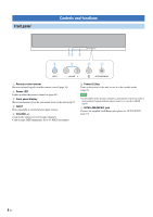
Rear panel 1 OUT HDMI IN 1 IN 2 IN 3 IN 4 FM ANTENNA 2 C B FRONT SURROUND SUR. BACK PRE OUT IR-OUT OUT 1 HDMI IN 1 IN 2 SUB IN 3 COMPONENT WOOFER SIRIUS SYSTEM PR PB LL CONNECTOR VIDEO Y VIDEO R R IN 4 IN OUT AUX 1 TV AUX 2 AUX 1 TV VIDEO AUDIO IN DIGITAL IN IR IN RS-232C 3 L L L CENTER R R R SUB WOOFER FRONT SURROUND SUR. BACK PRE OUT IR-OUT 45 A AC IN 67 8 90 SUB COMPONENT WOOFER SIRIUS SYSTEM CONNECTOR IN OUT AUX 1 TV AUX 2 VIDEO AUDIO IN AUX 1 TV DIGITAL IN IR IN RS-232C Note • The rear panel illustration shows jacks and their names to help you find them easily. They are not exactly the same as the ones on the actual rear panel of this unit. 1 HDMI jacks Connect your HDMI components (page 12). 2 FM ANTENNA jack Connect the FM antenna (page 14). 3 VIDEO jacks Connect to the video jacks of your external components (page 12). 4 SUBWOOFER jack Connect your subwoofer (page 13). 5 AUDIO IN jacks Connect to the analog audio output jacks of your external components (page 12). 6 SIRIUS antenna jack Connect a SiriusConnect tuner (sold separately) (page 26). 7 DIGITAL IN jacks Connect to the digital audio output jacks of your external components (page 12). 8 IR IN terminal This is a control expansion terminal for commercial use only. 9 SYSTEM CONNECTOR terminal Use to connect a Yamaha subwoofer equipped with a SYSTEM CONNECTOR terminal to this unit (page 13). 0 RS-232C terminal This is a control expansion terminal for commercial use only. A AC IN Connect the supplied power cable (page 12). B IR-OUT terminal This is a control expansion terminal for commercial use only. C PRE OUT jacks Connect your external amplifier (page 41). 8 En
-
 1
1 -
2
-
 3
3 -
 4
4 -
 5
5 -
 6
6 -
 7
7 -
 8
8 -
 9
9 -
 10
10 -
 11
11 -
 12
12 -
 13
13 -
14
-
15
-
16
-
17
-
18
-
19
-
20
-
21
-
22
-
23
-
24
-
25
-
26
-
27
-
28
-
29
-
30
-
31
-
32
-
33
-
34
-
35
-
36
-
37
-
38
-
39
-
40
-
41
-
42
-
43
-
44
-
45
-
46
-
47
-
48
-
49
-
50
-
51
-
52
-
53
-
54
-
55
-
56
-
57
-
58
 |
 |
