Yamaha YSP 900 Owner's Manual - Page 22
Connecting a digital satellite tuner or a cable TV tuner - support
 |
UPC - 027108928302
View all Yamaha YSP 900 manuals
Add to My Manuals
Save this manual to your list of manuals |
Page 22 highlights
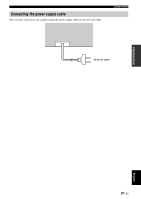
CONNECTIONS Connecting a digital satellite tuner or a cable TV tuner To connect a digital satellite tuner or a cable TV tuner, connect the optical digital output jack on your digital satellite tuner or cable TV tuner to the optical digital input jack (TV/STB OPTICAL) on this unit. In addition, connect the analog audio output jacks on your VCR to the analog audio input jacks (TV/STB R/L) on this unit. Connect red plugs to the right jacks and white plugs to the left jacks. y To prevent the optical cable from being unplugged, affix the optical cable in the supplied cable clamp (see page 14). Note If your TV and tuner connected to this unit do not support digital broadcasting, connect the analog audio output jacks (TV/STB R/L) on this unit to the analog audio output jacks on your TV. TV Digital satellite tuner or a cable TV tuner Analog audio output R L Video signal to a TV Analog audio output R L Optical digital output Rear panel of this unit VCR TV/STB SUBWOOFER VIDEO AUDIO INPUT OUT TV/STB AUX OPTICAL DVD COAXIAL DIGITAL INPUT Cables used for connections Optical cable (supplied) (White) (Red) Audio pin cable 18 En (White) (Red)
-
 1
1 -
2
-
3
-
4
-
5
-
6
-
7
-
8
-
9
-
10
-
11
-
12
-
13
-
14
-
15
-
16
-
 17
17 -
 18
18 -
 19
19 -
 20
20 -
 21
21 -
 22
22 -
 23
23 -
 24
24 -
 25
25 -
 26
26 -
 27
27 -
28
-
29
-
30
-
31
-
32
-
33
-
34
-
35
-
36
-
37
-
38
-
39
-
40
-
41
-
42
-
43
-
44
-
45
-
46
-
47
-
48
-
49
-
50
-
51
-
52
-
53
-
54
-
55
-
56
-
57
-
58
-
59
-
60
-
61
-
62
-
63
-
64
-
65
-
66
-
67
-
68
-
69
-
70
-
71
-
72
-
73
-
74
-
75
-
76
-
77
-
78
-
79
-
80
-
81
-
82
-
83
-
84
-
85
-
86
-
87
-
88
-
89
-
90
-
91
-
92
-
93
-
94
-
95
-
96
 |
 |
