Yamaha YSP 900 Owner's Manual - Page 64
BEAM ADJUSTMENT Beam adjustment, ASETTING PARAMETERS 2/3
 |
UPC - 027108928302
View all Yamaha YSP 900 manuals
Add to My Manuals
Save this manual to your list of manuals |
Page 64 highlights
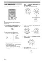
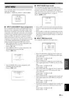
MANUAL SETUP • Select ANGLE TO WALL OR CORNER if this unit is installed in the corner in your listening room. Adjust the width and length of your listening room as well as the distance of the listening position from this unit. Listening position from the unit Room width ■ BEAM ADJUSTMENT (Beam adjustment) Use to manually adjust the various beam settings. We recommend that you select 5 beam as the beam mode before adjusting these parameters. Notes • When INSTALLED POSITION is adjusted in MANUAL SETUP (see page 59), the factory default value is automatically set for this parameter except CENTER in FOCAL LENGTH (see page 61). • Depending on the beam mode settings (see pages 40 and 46), some channel positions may not be available for selection. In this case, "- -" is displayed. When using the stereo plus 3 beam as the beam mode, set the surround left and right signals to be output from the front left and right channels. Room length Choices for the room width and length: 2.0 m (6.5 ft) to 12.0 m (40.0 ft) Choices for the listening position from this unit: 1.8 m (6.0 ft) to 9.0 m (30.0 ft) B)BEAM ADJUSTMENT . a)HORIZONTAL ANGLE b)BEAM TRAVEL LENGTH c)FOCAL LENGTH d)TREBLE GAIN [ ]/[ ]:Up/Down [ENTER]:Enter Room width and length p p A)SETTING PARAMETERS 2/3 ----- 5.4m --- | [ 5.4m ] | | p [ ]/[ ]:Up/Down [ ]/[ ]:Sel [ENTER]:Return HORIZONTAL ANGLE (Horizontal angle) Use to adjust the horizontal angle of beams for each channel. By adjusting the horizontal angle of the beams, you can optimize the sound beam paths. A test tone is automatically output. p p p p p p p Listening position from the unit p p A)SETTING PARAMETERS 3/3 \ [ 2.5m ] \ p [ ]/[ ]:Up/Down [ ]/[ ]:Sel [ENTER]:Return Note When you set the INSTALLED POSITION parameter in MANUAL SETUP (see page 59), the parameters newly set for the width and length of your listening room are automatically set as the factory default value. (−) (+) (+) (−) Choices: L90° to R90° Adjust towards L (left) to move the direction of the output to the left and adjust towards R (right) to move it to the right. a)HORIZONTAL ANGLE 1/5 5 beam Front L L65deg L90 R90 * p 0(deg) [ ]/[ ]:Up/Down [ ]/[ ]:Sel [ENTER]:Return 60 En
-
 1
1 -
2
-
3
-
4
-
5
-
6
-
7
-
8
-
9
-
10
-
11
-
12
-
13
-
14
-
15
-
16
-
17
-
18
-
19
-
20
-
21
-
22
-
23
-
24
-
25
-
26
-
27
-
28
-
29
-
30
-
31
-
32
-
33
-
34
-
35
-
36
-
37
-
38
-
39
-
40
-
41
-
42
-
43
-
44
-
45
-
46
-
47
-
48
-
49
-
50
-
51
-
52
-
53
-
54
-
55
-
56
-
57
-
58
-
 59
59 -
 60
60 -
 61
61 -
 62
62 -
 63
63 -
 64
64 -
 65
65 -
 66
66 -
 67
67 -
 68
68 -
 69
69 -
70
-
71
-
72
-
73
-
74
-
75
-
76
-
77
-
78
-
79
-
80
-
81
-
82
-
83
-
84
-
85
-
86
-
87
-
88
-
89
-
90
-
91
-
92
-
93
-
94
-
95
-
96
 |
 |
