Zenith H20H52DT Operating Guide - Page 11
Pillow Speaker Hook Up - remote control
 |
View all Zenith H20H52DT manuals
Add to My Manuals
Save this manual to your list of manuals |
Page 11 highlights
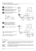
Pillow Speaker Hook Up Connect a Pillow Speaker to the HealthView TV. Locate the Pillow Speaker Output jack on 1 the back of the HealthView TV. Connect an accessory pillow speaker or 2 wired remote control unit to this 6-pin jack. Select PILLOW SPKR on the rear panel 3 of the HealthView TV. Use a pillow speaker by Curbell, Model A-1645502 or other UL recognized pendant control bearing the warning: "Risk of fire if used in oxygen enriched atmosphere. Keep pendant control away from TV oxygen equipment." TV Back ANTENNA CABLE TV SPEAKER M.P.I. PILLOW SPEAKER VIDEO IN SPEAKER OUT AUDIO IN TV Back Panel (Expanded View) Pillow speaker not included with HealtView TV. Controlling the TV with Serial Data The TV is capable of being controlled by a singlewire, serial data signal. This is a Zenith patented technology and is being implemented by certain brands of "smart" pillow speakers, such as Curbell's "GEN-II" models. Pillow Speaker Interface This connector furnishes three control lines and an audio output. A patient-pendant remote control, or entertainment audio and nurse call system may be connected here. All lines are isolated from the AC power line and earth ground. (Opto-isolators isolate the control lines, and a transformer isolates the audio. There are no relays or inductive components in the control lines). Pin no. 1 2 3 4 5 6 Purpose External TV On/Off switch (Not used) External Channel Up switch or Data in Common connection for control, data, and Audio output. Impedance to earth ground is a 8.2- meg resistor in parallel with a 1000 pf capacitor. Isolated audio output. Nominal 14-ohm source impedance with short circuit protection. Intended for a pillow speaker with a low-impedance pad-type volume control. External Channel Down switch SPKR. VOLUME CONTROL TV ON/OFF CHAN DOWN 4 5 63 1 2 (MALE PLUG) CHAN UP Controlling the TV with mechanical switches Pin 4 (common) is momentarily connected to pin 1, 3, or 6 via push-action switches to control On/Off and Channel Up/Down. These pins are at +13 volts DC (when measured from pin 4) with the switches open. Current draw is 8 mA when a switch is closed. (This operation using the 5-Wire Interface except that only +7 volts DC was supplied and current draw was only 2.5 mA). 1 4 2 5 6 3 3 1 4 2 5 6 TV ON/OFF OPEN CHAN UP/DATA IN COMMON AUDIO OUT CHAN DOWN Page 11
-
 1
1 -
2
-
3
-
4
-
5
-
 6
6 -
 7
7 -
 8
8 -
 9
9 -
 10
10 -
 11
11 -
 12
12 -
 13
13 -
 14
14 -
 15
15 -
 16
16 -
17
-
18
-
19
-
20
-
21
-
22
-
23
-
24
-
25
-
26
-
27
-
28
-
29
-
30
-
31
-
32
-
33
-
34
-
35
-
36
-
37
-
38
-
39
-
40
-
41
-
42
-
43
-
44
-
45
-
46
-
47
-
48
-
49
-
50
-
51
-
52
 |
 |
