Zenith XBR413 Operating Guide - Page 15
Connections Continued, Connecting to a TV
 |
UPC - 044642700652
View all Zenith XBR413 manuals
Add to My Manuals
Save this manual to your list of manuals |
Page 15 highlights
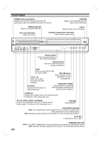
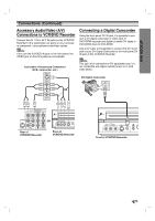
DVR HOOKUP Connections (Continued) Connecting to a TV Make one of the following connections, depending on the capabilities of your existing equipment. RF coaxial connection Connect the RF.OUT jack on the VCR/DVD Recorder to the antenna in jack on the TV using the 75-ohm Coaxial Cable supplied (R). ote If you use this connection, tune the TV to the VCR/DVD Recorder's RF output channel (CH 3 or 4). How to set the VCR/DVD Recorder's RF output channel When the VCR/DVD Recorder is turned off, press and hold CH (v/V) on the front panel for about five seconds to change the RF output channel (CH 03 or CH 04). "RF 03" or "RF 04" appears in the display window. Audio/Video connection 1 Connect the VIDEO OUT jack on the VCR/DVD Recorder to the video in jack on the TV using the video cable (V). 2 Connect the Left and Right AUDIO OUT jacks from the VCR/DVD Recorder to the audio left/right in jacks from the TV using the audio cables (A). Rear of TV ANTENNA INPUT S-VIDEO INPUT VIDEO INPUT AUDIO INPUT COMPONENT/PROGRESSIVE VIDEO INPUT L R Pr Pb Y S-Video connection 1 Connect the S-VIDEO OUT jack on the VCR/DVD Recorder to the S-Video in jack on the TV using the S-Video cable (S). 2 Connect the Left and Right AUDIO OUT jacks from the VCR/DVD Recorder to the audio left/right in jacks on the TV using the audio cables (A). Component Video (Color Stream®) connection 1 Connect the COMPONENT/PROGRESSIVE SCAN VIDEO OUT jacks on the VCR/DVD Recorder to the corresponding in jacks on the TV using an Y Pb Pr cable (C). 2 Connect the Left and Right AUDIO OUT jacks from the VCR/DVD Recorder to the audio left/right in jacks on the TV using the audio cables (A). Progressive Scan (ColorStream® pro) connection If your television is a high-definition or "digital ready" television, you may take advantage of the VCR/DVD Recorder's progressive scan output for the highest video resolution possible. If your TV does not accept the Progressive Scan format, the picture will appear scrambled if you try Progressive Scan on the VCR/DVD Recorder. 1 Connect the COMPONENT/PROGRESSIVE SCAN VIDEO OUT jacks on the VCR/DVD Recorder to the corresponding in jacks on the TV using an optional Y Pb Pr cable (C). 2 Connect the Left and Right AUDIO OUT jacks from the VCR/DVD Recorder to the audio left/right in jacks on the TV using the supplied audio cables (A). RS VA C otes - Set Progressive Scan option to "ON" in the General menu, see page 20. - Progressive Scan does not work with the RF, Audio/Video or S-Video connections. Rear of VCR/DVD Recorder 15
-
 1
1 -
2
-
3
-
4
-
5
-
6
-
7
-
8
-
9
-
 10
10 -
 11
11 -
 12
12 -
 13
13 -
 14
14 -
 15
15 -
 16
16 -
 17
17 -
 18
18 -
 19
19 -
 20
20 -
21
-
22
-
23
-
24
-
25
-
26
-
27
-
28
-
29
-
30
-
31
-
32
-
33
-
34
-
35
-
36
-
37
-
38
-
39
-
40
-
41
-
42
-
43
-
44
-
45
-
46
-
47
-
48
-
49
-
50
-
51
-
52
-
53
-
54
-
55
-
56
-
57
-
58
-
59
 |
 |
