Alcatel OS6850-P48 User Guide - Page 118
OmniSwitch 6850E-U24X, 100/1000BaseT RJ-45 Combo Ports and LEDs
 |
View all Alcatel OS6850-P48 manuals
Add to My Manuals
Save this manual to your list of manuals |
Page 118 highlights
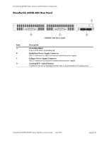
OmniSwitch 6850E-U24X OmniSwitch 6850E Series Chassis and Hardware Components AB C D EF G H OS6850E-U24X Front Panel Item A B C D E F G H Description LED Indicator Seven segment LED provides stack element ID. USB Port High speed USB port. System Status LEDs Provides status on hardware, software, primary and redundant power. SFP Ports and LEDs Combo and non-combo SFP connectors for various supported SFP transceivers. Console Port RS-232 console port with an RJ-45 connector. Provides access to the CLI for configuration and management. Rear Module Port LEDs Provides link and traffic status for rear modules. SFP+ Ports and LEDs Two non-combo SFP+ connectors for various supported SFP+ transceivers. 10/100/1000BaseT RJ-45 Combo Ports and LEDs 10/100/1000BaseT RJ-45 combo ports. Refer to "OmniSwitch 6850E LED Status Indicators" on page 3-31 for LED status information. Refer to "OmniSwitch 6850E Port Numbering" on page 3-30 for port numbering. page 3-26 OmniSwitch 6850/6850E Series Hardware Users Guide June 2011
-
 1
1 -
2
-
3
-
4
-
5
-
6
-
7
-
8
-
9
-
10
-
11
-
12
-
13
-
14
-
15
-
16
-
17
-
18
-
19
-
20
-
21
-
22
-
23
-
24
-
25
-
26
-
27
-
28
-
29
-
30
-
31
-
32
-
33
-
34
-
35
-
36
-
37
-
38
-
39
-
40
-
41
-
42
-
43
-
44
-
45
-
46
-
47
-
48
-
49
-
50
-
51
-
52
-
53
-
54
-
55
-
56
-
57
-
58
-
59
-
60
-
61
-
62
-
63
-
64
-
65
-
66
-
67
-
68
-
69
-
70
-
71
-
72
-
73
-
74
-
75
-
76
-
77
-
78
-
79
-
80
-
81
-
82
-
83
-
84
-
85
-
86
-
87
-
88
-
89
-
90
-
91
-
92
-
93
-
94
-
95
-
96
-
97
-
98
-
99
-
100
-
101
-
102
-
103
-
104
-
105
-
106
-
107
-
108
-
109
-
110
-
111
-
112
-
 113
113 -
 114
114 -
 115
115 -
 116
116 -
 117
117 -
 118
118 -
 119
119 -
 120
120 -
 121
121 -
 122
122 -
 123
123 -
124
-
125
-
126
-
127
-
128
-
129
-
130
-
131
-
132
-
133
-
134
-
135
-
136
-
137
-
138
-
139
-
140
-
141
-
142
-
143
-
144
-
145
-
146
-
147
-
148
-
149
-
150
-
151
-
152
-
153
-
154
-
155
-
156
-
157
-
158
-
159
-
160
-
161
-
162
-
163
-
164
-
165
-
166
-
167
-
168
-
169
-
170
-
171
-
172
-
173
-
174
-
175
-
176
-
177
-
178
-
179
-
180
-
181
-
182
-
183
-
184
-
185
-
186
-
187
-
188
-
189
-
190
-
191
-
192
-
193
-
194
-
195
-
196
-
197
-
198
-
199
-
200
-
201
-
202
-
203
-
204
-
205
-
206
-
207
-
208
-
209
-
210
-
211
-
212
-
213
-
214
-
215
-
216
-
217
-
218
-
219
-
220
 |
 |
