Alcatel OS6850-P48 User Guide - Page 51
OmniSwitch 6850-24X Front Panel, Console Port, Status and Slot Indicator LEDs, USB Port, Combo SFP
 |
View all Alcatel OS6850-P48 manuals
Add to My Manuals
Save this manual to your list of manuals |
Page 51 highlights
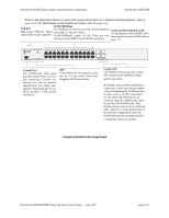
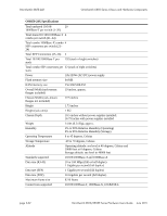
OmniSwitch 6850 Series Chassis and Hardware Components OmniSwitch 6850-24X Refer to the illustration below for more front panel information. For detailed LED descriptions, refer to page 2-53. For information on the chassis rear panel, refer to page 2-55. 10/100/1000Mbps USB Port High speed USB port, which can be used for quick upgrades. The OS6850-24X provides 20 fixed 10/100/1000BaseT non-combo (1-20) and 4 fixed 10/100/1000BaseT combo (21-24). These are auto- Status and Slot Indicator LEDs For information on the OS6850-24X's status and slot indicator LEDs, refer to sensing and auto-MDIX and use RJ-45 connectors. page 2-53. OmniSwitch 6850-24X USB OK PRI PWR BPS 25 26 Console 25 26 CLASS 1 LASER PRODUCT 1 2 3 4 5 6 7 8 9 10 11 12 13 14 15 16 17 18 19 20 21 22 23 24 21 22 23 24 CLASS 1 LASER PRODUCT Console Port The OS6850-24X front panel provides one RJ-45 port for console connections. Console connections are used by network administrators for switch management. This female RJ-45 connector provides a DTE console connection. XFP The OS6850-24X front panel provides two for 10 Gbps Small Form Factor Pluggable (XFP) transceivers. Combo SFP The OS6850-24X provides four combo SFP connectors for 1000Base-X high- speed connections. By default, when an SFP is installed in a combo port, it takes over the port number of the corresponding RJ-45 Ethernet port. In other words, if an SFP is installed in the slot labeled 24, Ethernet port 24 would no longer be available and cannot be used for 10/100/1000 traffic. This default setting is referred to as "preferred fiber." Refer to "Configuring Ethernet" in the Network Configuration Guide for detailed information, including steps for configuring combo port settings. OmniSwitch 6850-24X Front Panel OmniSwitch 6850/6850E Series Hardware Users Guide June 2011 page 2-31
-
 1
1 -
2
-
3
-
4
-
5
-
6
-
7
-
8
-
9
-
10
-
11
-
12
-
13
-
14
-
15
-
16
-
17
-
18
-
19
-
20
-
21
-
22
-
23
-
24
-
25
-
26
-
27
-
28
-
29
-
30
-
31
-
32
-
33
-
34
-
35
-
36
-
37
-
38
-
39
-
40
-
41
-
42
-
43
-
44
-
45
-
 46
46 -
 47
47 -
 48
48 -
 49
49 -
 50
50 -
 51
51 -
 52
52 -
 53
53 -
 54
54 -
 55
55 -
 56
56 -
57
-
58
-
59
-
60
-
61
-
62
-
63
-
64
-
65
-
66
-
67
-
68
-
69
-
70
-
71
-
72
-
73
-
74
-
75
-
76
-
77
-
78
-
79
-
80
-
81
-
82
-
83
-
84
-
85
-
86
-
87
-
88
-
89
-
90
-
91
-
92
-
93
-
94
-
95
-
96
-
97
-
98
-
99
-
100
-
101
-
102
-
103
-
104
-
105
-
106
-
107
-
108
-
109
-
110
-
111
-
112
-
113
-
114
-
115
-
116
-
117
-
118
-
119
-
120
-
121
-
122
-
123
-
124
-
125
-
126
-
127
-
128
-
129
-
130
-
131
-
132
-
133
-
134
-
135
-
136
-
137
-
138
-
139
-
140
-
141
-
142
-
143
-
144
-
145
-
146
-
147
-
148
-
149
-
150
-
151
-
152
-
153
-
154
-
155
-
156
-
157
-
158
-
159
-
160
-
161
-
162
-
163
-
164
-
165
-
166
-
167
-
168
-
169
-
170
-
171
-
172
-
173
-
174
-
175
-
176
-
177
-
178
-
179
-
180
-
181
-
182
-
183
-
184
-
185
-
186
-
187
-
188
-
189
-
190
-
191
-
192
-
193
-
194
-
195
-
196
-
197
-
198
-
199
-
200
-
201
-
202
-
203
-
204
-
205
-
206
-
207
-
208
-
209
-
210
-
211
-
212
-
213
-
214
-
215
-
216
-
217
-
218
-
219
-
220
 |
 |
