Asus NCCH-DLE NCCH-DLE User's Manual English version 1.0 - Page 24
Support plates for motherboard
 |
View all Asus NCCH-DLE manuals
Add to My Manuals
Save this manual to your list of manuals |
Page 24 highlights
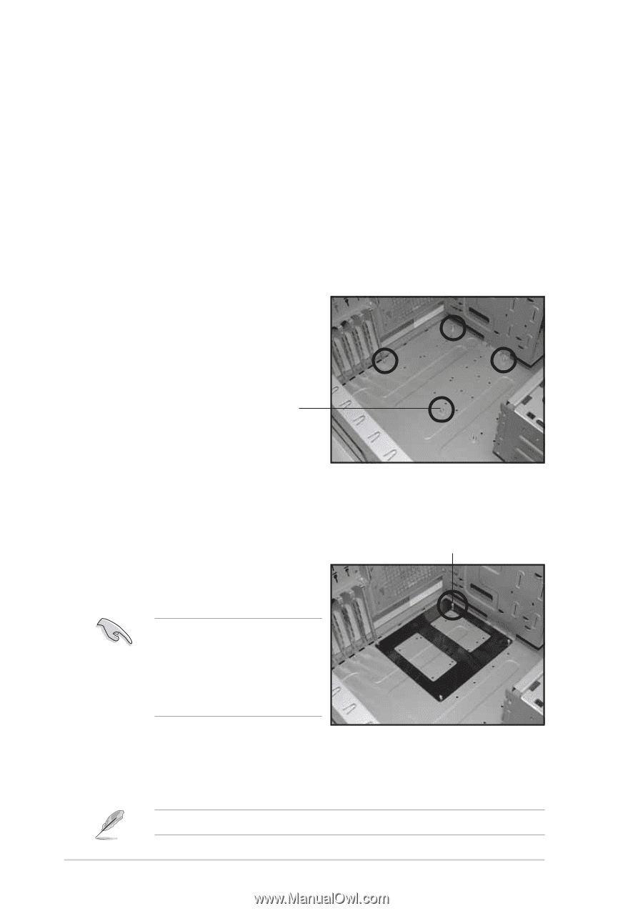
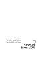
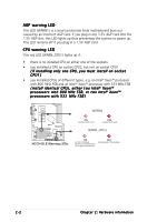
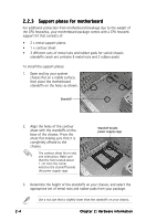
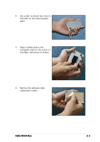
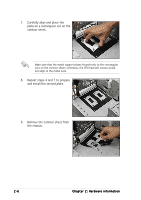
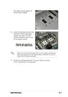
2.2.3 Support plates for motherboard For additional protection from motherboard breakage due to the weight of the CPU heatsinks, your motherboard package comes with a CPU heatsink support kit that consists of: • 2 x metal support plates • 1 x contour sheet • 3 different sets of metal nuts and rubber pads for varied chassis standoffs (each set contains 8 metal nuts and 2 rubber pads) To install the support plates: 1. Open and lay your system chassis flat on a stable surface, then place the motherboard standoffs on the holes as shown. Standoff 2. Align the holes of the contour sheet with the standoffs on the base of the chassis. Press the sheet flat making sure that it is completely affixed to the chassis. The contour sheet fits in only one orientation. Make sure that the hole located about 1 cm from the corner matches the standoff beside the power supply cage. Standoff beside power supply cage 3. Determine the height of the standoffs on your chassis, and select the appropriate set of metal nuts and rubber pads from your package. Use a nut size that is slightly lower than the standoffs on your chassis. 2-4 Chapter 2: Hardware information
-
 1
1 -
2
-
3
-
4
-
5
-
6
-
7
-
8
-
9
-
10
-
11
-
12
-
13
-
14
-
15
-
16
-
17
-
18
-
 19
19 -
 20
20 -
 21
21 -
 22
22 -
 23
23 -
 24
24 -
 25
25 -
 26
26 -
 27
27 -
 28
28 -
 29
29 -
30
-
31
-
32
-
33
-
34
-
35
-
36
-
37
-
38
-
39
-
40
-
41
-
42
-
43
-
44
-
45
-
46
-
47
-
48
-
49
-
50
-
51
-
52
-
53
-
54
-
55
-
56
-
57
-
58
-
59
-
60
-
61
-
62
-
63
-
64
-
65
-
66
-
67
-
68
-
69
-
70
-
71
-
72
-
73
-
74
-
75
-
76
-
77
-
78
-
79
-
80
-
81
-
82
-
83
-
84
-
85
-
86
-
87
-
88
-
89
-
90
-
91
-
92
-
93
-
94
-
95
-
96
-
97
-
98
-
99
-
100
-
101
-
102
-
103
-
104
-
105
-
106
-
107
-
108
-
109
-
110
-
111
-
112
-
113
-
114
-
115
-
116
-
117
-
118
-
119
-
120
-
121
-
122
-
123
-
124
-
125
-
126
-
127
-
128
-
129
-
130
-
131
-
132
-
133
-
134
-
135
-
136
-
137
-
138
-
139
-
140
-
141
-
142
-
143
-
144
-
145
-
146
-
147
-
148
-
149
-
150
-
151
-
152
-
153
-
154
-
155
-
156
-
157
-
158
-
159
-
160
-
161
-
162
-
163
-
164
-
165
-
166
-
167
-
168
-
169
-
170
-
171
-
172
-
173
-
174
-
175
-
176
-
177
-
178
-
179
-
180
 |
 |