Asus NCCH-DLE NCCH-DLE User's Manual English version 1.0 - Page 45
Connectors
 |
View all Asus NCCH-DLE manuals
Add to My Manuals
Save this manual to your list of manuals |
Page 45 highlights
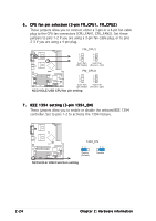
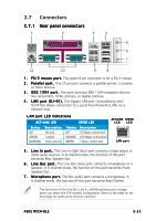
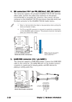
2.7 Connectors 2.7.1 Rear panel connectors 1 2 3 4 5 6 7 11 10 9 8 1 . P S / 2 m o u s e p o r t . This green 6-pin connector is for a PS/2 mouse. 2 . P a r a l l e l p o r t . This 25-pin port connects a parallel printer, a scanner, or other devices. 3 . I E E E 1 3 9 4 p o r t . This port connects IEEE 1394-compliant devices like camcorders, VCRs, printers, or digital cameras. 4 . L A N p o r t ( R J - 4 5 ) . This Gigabit LAN port (controlled by Intel 82547GI) allows connection to a Local Area Network (LAN) via a network hub. LAN port LED indications ACT/LINK LED SPEED LED Status Description Status Description OFF GREEN BLINKING No link Linked Data activity OFF ORANGE GREEN 10 Mbps connection 100 Mbps connection 1 Gbps connection ACT/LINK SPEED LED LED LAN port 5 . L i n e I n p o r t . This Line In (light blue) port connects a tape player or other audio sources. In 6-channel mode, the function of this port becomes Rear Speaker Out. 6 . L i n e O u t p o r t . This Line Out (lime) port connects a headphone or a speaker. In 6-channel mode, the function of this port becomes Front Speaker Out. 7 . M i c r o p h o n e p o r t . This Mic (pink) port connects a microphone. In 6-channel mode, the function of this port becomes Bass/Center. The functions of the Line Out, Line In, and Microphone ports change when you select the 4/6-channel configuration. Refer to the table on the next page for audio ports function variation. ASUS NCCH-DLE 2-25
-
 1
1 -
2
-
3
-
4
-
5
-
6
-
7
-
8
-
9
-
10
-
11
-
12
-
13
-
14
-
15
-
16
-
17
-
18
-
19
-
20
-
21
-
22
-
23
-
24
-
25
-
26
-
27
-
28
-
29
-
30
-
31
-
32
-
33
-
34
-
35
-
36
-
37
-
38
-
39
-
 40
40 -
 41
41 -
 42
42 -
 43
43 -
 44
44 -
 45
45 -
 46
46 -
 47
47 -
 48
48 -
 49
49 -
 50
50 -
51
-
52
-
53
-
54
-
55
-
56
-
57
-
58
-
59
-
60
-
61
-
62
-
63
-
64
-
65
-
66
-
67
-
68
-
69
-
70
-
71
-
72
-
73
-
74
-
75
-
76
-
77
-
78
-
79
-
80
-
81
-
82
-
83
-
84
-
85
-
86
-
87
-
88
-
89
-
90
-
91
-
92
-
93
-
94
-
95
-
96
-
97
-
98
-
99
-
100
-
101
-
102
-
103
-
104
-
105
-
106
-
107
-
108
-
109
-
110
-
111
-
112
-
113
-
114
-
115
-
116
-
117
-
118
-
119
-
120
-
121
-
122
-
123
-
124
-
125
-
126
-
127
-
128
-
129
-
130
-
131
-
132
-
133
-
134
-
135
-
136
-
137
-
138
-
139
-
140
-
141
-
142
-
143
-
144
-
145
-
146
-
147
-
148
-
149
-
150
-
151
-
152
-
153
-
154
-
155
-
156
-
157
-
158
-
159
-
160
-
161
-
162
-
163
-
164
-
165
-
166
-
167
-
168
-
169
-
170
-
171
-
172
-
173
-
174
-
175
-
176
-
177
-
178
-
179
-
180
 |
 |
