Asus P3V133 P3V133 User Manual - Page 14
Hardware Setup - detail
 |
View all Asus P3V133 manuals
Add to My Manuals
Save this manual to your list of manuals |
Page 14 highlights
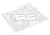
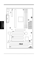
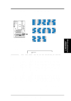
3. H/W SETUP Motherboard Layout 3. HARDWARE SETUP 3.1 P3V133 Motherboard Layout 19.2cm (7.6in) Parallel Port ATX Power Connector CPU Slot 1 PS2 KBMS TOP: Mouse BOTTOM: Keyboard USB KBPWR TOP: USB 1 BOTTOM: USB 2 COM1 PWR_FAN CPU_FAN VIA VT82C693A Chipset BUS FREQ FS3 FS2 FS1 FS0 MS0 MS1 COM2 DIMM Socket 1 (64/72 bit, 168 pin module) DIMM Socket 2 (64/72 bit, 168 pin module) DIMM Socket 3 (64/72 bit, 168 pin module) VIO VCORE Row 0 1 2 3 4 5 JTCPU WOL_CON Accelerated Graphics Port Multi-I/O CHASIS PCI Slot 1 PCI Slot 2 PCI Slot 3 2Mb Flash EEPROM (Programable BIOS) JTPWR Hardware Monitor SMB PCI Slot 4 ISA Slot 1 P3V133 R ISA Slot 2 ISA Slot 3 CR2032 3V Lithium Cell (CMOS Power) CHA_FAN CLRTC VIA VT82C596B PCIset WOR BF3 BF2 BF1 BF0 FREQ MULT ASUS ASIC IR IDE LED PANEL FLOPPY SECONDARY IDE PRIMARY IDE 30.5cm (12.0in) 14 ASUS P3V133 User's Manual
-
 1
1 -
2
-
3
-
4
-
5
-
6
-
7
-
8
-
 9
9 -
 10
10 -
 11
11 -
 12
12 -
 13
13 -
 14
14 -
 15
15 -
 16
16 -
 17
17 -
 18
18 -
 19
19 -
20
-
21
-
22
-
23
-
24
-
25
-
26
-
27
-
28
-
29
-
30
-
31
-
32
-
33
-
34
-
35
-
36
-
37
-
38
-
39
-
40
-
41
-
42
-
43
-
44
-
45
-
46
-
47
-
48
-
49
-
50
-
51
-
52
-
53
-
54
-
55
-
56
-
57
-
58
-
59
-
60
-
61
-
62
-
63
-
64
-
65
-
66
-
67
-
68
-
69
-
70
-
71
-
72
-
73
-
74
-
75
-
76
-
77
-
78
-
79
-
80
-
81
-
82
-
83
-
84
-
85
-
86
-
87
-
88
-
89
-
90
-
91
-
92
-
93
-
94
-
95
-
96
 |
 |
