Asus P3V133 P3V133 User Manual - Page 33
Serial Port COM1 and COM2 Connectors Two 9-pin male
 |
View all Asus P3V133 manuals
Add to My Manuals
Save this manual to your list of manuals |
Page 33 highlights
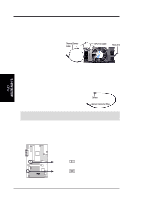
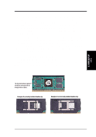
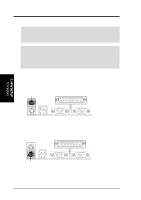
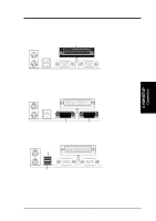
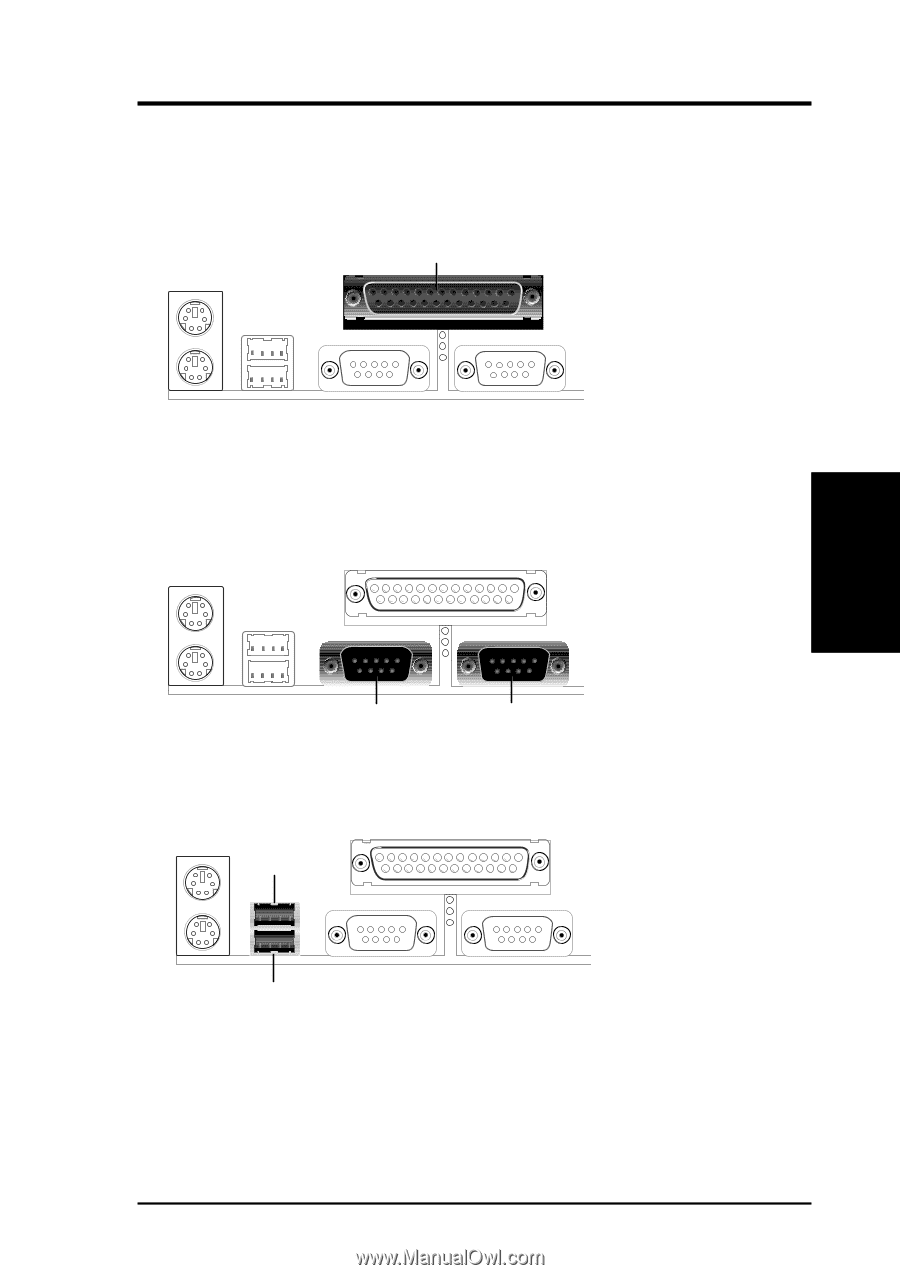
3. H/W SETUP D CMoAnCnhecatnonrsels 3. HARDWARE SETUP 3. Parallel Port Connector (25-pin female) You can enable the parallel port and choose the IRQ through "Onboard Parallel Port" in Chipset Features Setup of BIOS SETUP. NOTE: Serial printers must be connected to the serial port. Parallel (Printer) Port (25-pin Female) 4. Serial Port COM1 and COM2 Connectors (Two 9-pin male) The two serial ports can be used for pointing devices or other serial devices. See "Onboard Serial Port" in Chipset Features Setup of BIOS SETUP. COM 1 COM 2 Serial Ports (9-pin Male) 5. Universal Serial BUS Port Connectors 1 & 2 (Two 4-pin female) Two USB ports are available for connecting USB devices. USB 1 Universal Serial Bus (USB) 2 ASUS P3V133 User's Manual 33
-
 1
1 -
2
-
3
-
4
-
5
-
6
-
7
-
8
-
9
-
10
-
11
-
12
-
13
-
14
-
15
-
16
-
17
-
18
-
19
-
20
-
21
-
22
-
23
-
24
-
25
-
26
-
27
-
 28
28 -
 29
29 -
 30
30 -
 31
31 -
 32
32 -
 33
33 -
 34
34 -
 35
35 -
 36
36 -
 37
37 -
 38
38 -
39
-
40
-
41
-
42
-
43
-
44
-
45
-
46
-
47
-
48
-
49
-
50
-
51
-
52
-
53
-
54
-
55
-
56
-
57
-
58
-
59
-
60
-
61
-
62
-
63
-
64
-
65
-
66
-
67
-
68
-
69
-
70
-
71
-
72
-
73
-
74
-
75
-
76
-
77
-
78
-
79
-
80
-
81
-
82
-
83
-
84
-
85
-
86
-
87
-
88
-
89
-
90
-
91
-
92
-
93
-
94
-
95
-
96
 |
 |
ASUS P3V133 User’s Manual
33
3. HARDWARE SETUP
DMA Channels
3. H/W SETUP
Connectors
3. H/W SETUP
3.
Parallel Port Connector (25-pin female)
You can enable the parallel port and choose the IRQ through “Onboard Parallel
Port” in
Chipset Features Setup
of BIOS SETUP.
NOTE
: Serial printers must
be connected to the serial port.
Parallel (Printer) Port (25-pin Female)
4.
Serial Port COM1 and COM2 Connectors (Two 9-pin male)
The two serial ports can be used for pointing devices or other serial devices. See
“Onboard Serial Port” in
Chipset Features Setup
of BIOS SETUP.
COM 1
COM 2
Serial Ports (9-pin Male)
5.
Universal Serial BUS Port Connectors 1 & 2 (Two 4-pin female)
Two USB ports are available for connecting USB devices.
Universal Serial Bus (USB) 2
USB 1