Asus P3V133 P3V133 User Manual - Page 17
H/w Setup - overclock
 |
View all Asus P3V133 manuals
Add to My Manuals
Save this manual to your list of manuals |
Page 17 highlights
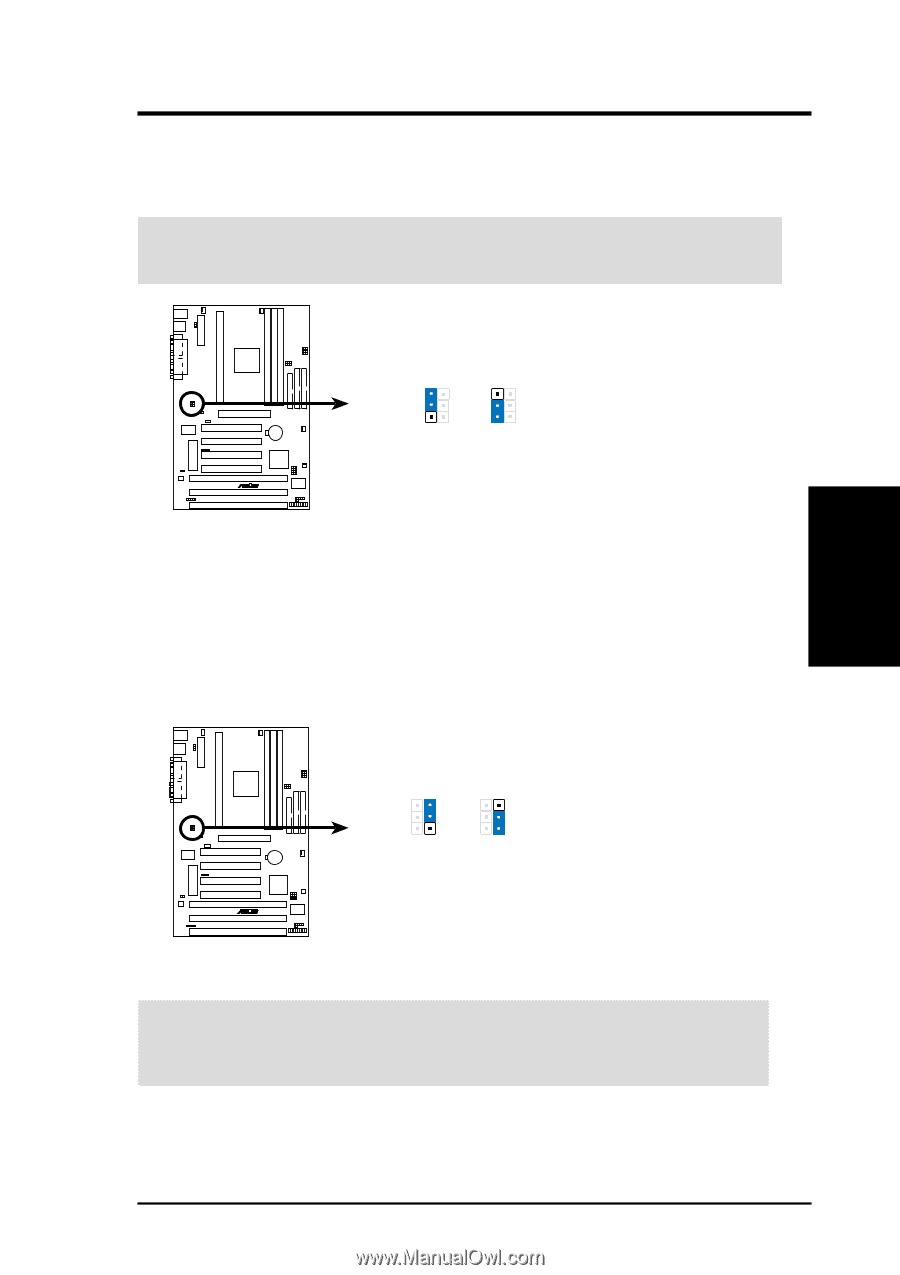
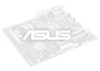
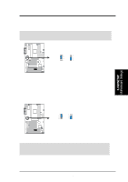
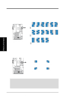
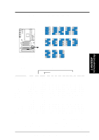
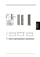
3. H/W SETUP Motherboard Settings 3. HARDWARE SETUP 2. I/O Voltage Setting (VIO) This jumper allows you to select the voltage supplied to the DRAM, chipset, AGP, and the CPU's I/O buffer. IMPORTANT: Setting this jumper to Test may reduce system life. Leave on default setting of Normal. P3V133 R VIO 3 2 1 Normal (Default) 3 2 1 Test P3V133 Input/Output Voltage Selection 3. Voltage Regulator Output Setting (VCORE) This jumper sets the core voltage supplied to the microprocessor. VCORE 3 2 1 Normal (Default) 3 2 1 Test P3V133 R P3V133 CPU Core Voltage Selection WARNING! Using a higher voltage Test may help when overclocking but may result in the shortening of your computer component's life. It is strongly recommended that you leave both the VIO and VCORE jumpers on their default settings. ASUS P3V133 User's Manual 17
-
 1
1 -
2
-
3
-
4
-
5
-
6
-
7
-
8
-
9
-
10
-
11
-
 12
12 -
 13
13 -
 14
14 -
 15
15 -
 16
16 -
 17
17 -
 18
18 -
 19
19 -
 20
20 -
 21
21 -
 22
22 -
23
-
24
-
25
-
26
-
27
-
28
-
29
-
30
-
31
-
32
-
33
-
34
-
35
-
36
-
37
-
38
-
39
-
40
-
41
-
42
-
43
-
44
-
45
-
46
-
47
-
48
-
49
-
50
-
51
-
52
-
53
-
54
-
55
-
56
-
57
-
58
-
59
-
60
-
61
-
62
-
63
-
64
-
65
-
66
-
67
-
68
-
69
-
70
-
71
-
72
-
73
-
74
-
75
-
76
-
77
-
78
-
79
-
80
-
81
-
82
-
83
-
84
-
85
-
86
-
87
-
88
-
89
-
90
-
91
-
92
-
93
-
94
-
95
-
96
 |
 |