Asus TS300-E4 PX4 User Guide - Page 32
System memory
 |
View all Asus TS300-E4 PX4 manuals
Add to My Manuals
Save this manual to your list of manuals |
Page 32 highlights
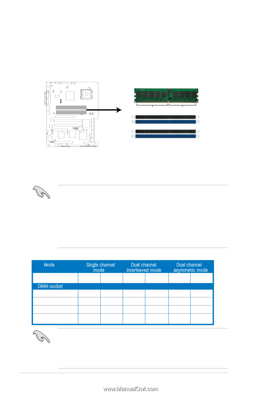
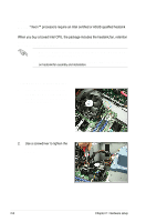
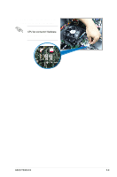
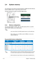
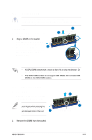
2.4 System memory 2.4.1 Overview The motherboard comes with four Double Data Rate II (DDR2) Dual Inline Memory Modules (DIMM) sockets to support 240-pin DDR modules. The figure illustrates the location of the DDR DIMM sockets: ® P5M2 128 Pins 112 Pins DIMM_A1 DIMM_A2 DIMM_B1 DIMM_B2 P5M2 240-pin DDR2 DIMM Sockets 2.4.2 Memory configurations You may install 256 MB, 512 MB, 1 GB, and 2 GB unbuffered ECC or non‑ECC DDR2-533/667 DIMMs into the DIMM sockets. • Always install DIMMs with the same CAS latency. For optimum compatibility, it is recommended that you obtain memory modules from the same vendor. Refer to the DDR2 Qualified Vendors List at the ASUS web site. • When installing one or two DIMMs, install the DIMM(s) to the blue slots (DIMM_A2/DIMM_B2). • Three DDR DIMMs intalled into any three memory sockets will function in dual-channel asmmetric mode. Recommended memory configurations Mode Single channel mode Dual channel interleaved mode Dual channel asymmetic mode Number of memories 1 1 2 4* 3 4* DIMM socket DIMM_A1 V V V DIMM_A2 V V V V V DIMM_B1 V V DIMM_B2 V V V V V • When the total size of memory module(s) installed per channel is the same (A1+A2=B1+B2), the system will run in Dual Channel Interleaved mode which provides optimum performance. • When the total size of each channel is not the same (A1+A2≠B1+B2), the system will run in Dual Channel Asymmetric mode. 2-10 Chapter 2: Hardware setup
-
 1
1 -
2
-
3
-
4
-
5
-
6
-
7
-
8
-
9
-
10
-
11
-
12
-
13
-
14
-
15
-
16
-
17
-
18
-
19
-
20
-
21
-
22
-
23
-
24
-
25
-
26
-
 27
27 -
 28
28 -
 29
29 -
 30
30 -
 31
31 -
 32
32 -
 33
33 -
 34
34 -
 35
35 -
 36
36 -
 37
37 -
38
-
39
-
40
-
41
-
42
-
43
-
44
-
45
-
46
-
47
-
48
-
49
-
50
-
51
-
52
-
53
-
54
-
55
-
56
-
57
-
58
-
59
-
60
-
61
-
62
-
63
-
64
-
65
-
66
-
67
-
68
-
69
-
70
-
71
-
72
-
73
-
74
-
75
-
76
-
77
-
78
-
79
-
80
-
81
-
82
-
83
-
84
-
85
-
86
-
87
-
88
-
89
-
90
-
91
-
92
-
93
-
94
-
95
-
96
-
97
-
98
-
99
-
100
-
101
-
102
-
103
-
104
-
105
-
106
-
107
-
108
-
109
-
110
-
111
-
112
-
113
-
114
-
115
-
116
-
117
-
118
-
119
-
120
-
121
-
122
-
123
-
124
-
125
-
126
-
127
-
128
-
129
-
130
-
131
-
132
-
133
-
134
-
135
-
136
-
137
-
138
-
139
-
140
-
141
-
142
-
143
-
144
-
145
-
146
-
147
-
148
-
149
-
150
-
151
-
152
-
153
-
154
-
155
-
156
-
157
-
158
-
159
-
160
-
161
-
162
-
163
-
164
-
165
-
166
-
167
-
168
-
169
-
170
-
171
-
172
-
173
-
174
-
175
-
176
-
177
-
178
-
179
-
180
-
181
-
182
-
183
-
184
-
185
-
186
-
187
-
188
-
189
-
190
-
191
-
192
-
193
-
194
-
195
-
196
-
197
-
198
-
199
-
200
-
201
-
202
-
203
-
204
-
205
-
206
-
207
-
208
-
209
-
210
-
211
-
212
-
213
-
214
-
215
-
216
-
217
-
218
-
219
-
220
-
221
-
222
-
223
-
224
 |
 |