Asus TS300-E4 PX4 User Guide - Page 46
SATA backplane connections
 |
View all Asus TS300-E4 PX4 manuals
Add to My Manuals
Save this manual to your list of manuals |
Page 46 highlights
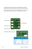
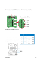
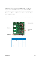
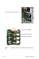
2.9.2 SATA backplane connections (in PA4 model only) A SATA backplane comes pre-installed in the TS300-E4/PA4 model. The SATA backplane has four 22-pin SATA connectors to support Serial ATA hard disk drives. The backplane design incorporates a hot swap feature to allow easy connection or removal of SATA hard disks. The LEDs on the backplane connect to the front panel LEDs to indicate HDD status. See section "1.6 LED information" for details. Front side The front side of the SATA backplane faces the front panel when installed. This side includes four SATA connectors for the hot swap drive trays. (SATA Port0 CON1) (SATA Port1 CON3) (SATA Port2 CON5) (SATA Port3 CON7) Each SATA connector is labeled (CON1, CON3, CON5, CON7) so you can easily determine their counterpart connectors at the back side of the backplane. Refer to the table for reference. Drive status LEDs HDD Device HDD 1 HDD 2 HDD 3 HDD 4 Front side connector CON1 CON3 CON5 CON7 Back side connector CON2 CON4 CON6 CON8 SATA Port number Port0 Port1 Port2 Port3 2-24 Chapter 2: Hardware setup
-
 1
1 -
2
-
3
-
4
-
5
-
6
-
7
-
8
-
9
-
10
-
11
-
12
-
13
-
14
-
15
-
16
-
17
-
18
-
19
-
20
-
21
-
22
-
23
-
24
-
25
-
26
-
27
-
28
-
29
-
30
-
31
-
32
-
33
-
34
-
35
-
36
-
37
-
38
-
39
-
40
-
 41
41 -
 42
42 -
 43
43 -
 44
44 -
 45
45 -
 46
46 -
 47
47 -
 48
48 -
 49
49 -
 50
50 -
 51
51 -
52
-
53
-
54
-
55
-
56
-
57
-
58
-
59
-
60
-
61
-
62
-
63
-
64
-
65
-
66
-
67
-
68
-
69
-
70
-
71
-
72
-
73
-
74
-
75
-
76
-
77
-
78
-
79
-
80
-
81
-
82
-
83
-
84
-
85
-
86
-
87
-
88
-
89
-
90
-
91
-
92
-
93
-
94
-
95
-
96
-
97
-
98
-
99
-
100
-
101
-
102
-
103
-
104
-
105
-
106
-
107
-
108
-
109
-
110
-
111
-
112
-
113
-
114
-
115
-
116
-
117
-
118
-
119
-
120
-
121
-
122
-
123
-
124
-
125
-
126
-
127
-
128
-
129
-
130
-
131
-
132
-
133
-
134
-
135
-
136
-
137
-
138
-
139
-
140
-
141
-
142
-
143
-
144
-
145
-
146
-
147
-
148
-
149
-
150
-
151
-
152
-
153
-
154
-
155
-
156
-
157
-
158
-
159
-
160
-
161
-
162
-
163
-
164
-
165
-
166
-
167
-
168
-
169
-
170
-
171
-
172
-
173
-
174
-
175
-
176
-
177
-
178
-
179
-
180
-
181
-
182
-
183
-
184
-
185
-
186
-
187
-
188
-
189
-
190
-
191
-
192
-
193
-
194
-
195
-
196
-
197
-
198
-
199
-
200
-
201
-
202
-
203
-
204
-
205
-
206
-
207
-
208
-
209
-
210
-
211
-
212
-
213
-
214
-
215
-
216
-
217
-
218
-
219
-
220
-
221
-
222
-
223
-
224
 |
 |
