Biostar M7VKG M7VKG user's manual - Page 13
Front Panel Connectors (JPANEL1 / JPANEL2
 |
View all Biostar M7VKG manuals
Add to My Manuals
Save this manual to your list of manuals |
Page 13 highlights
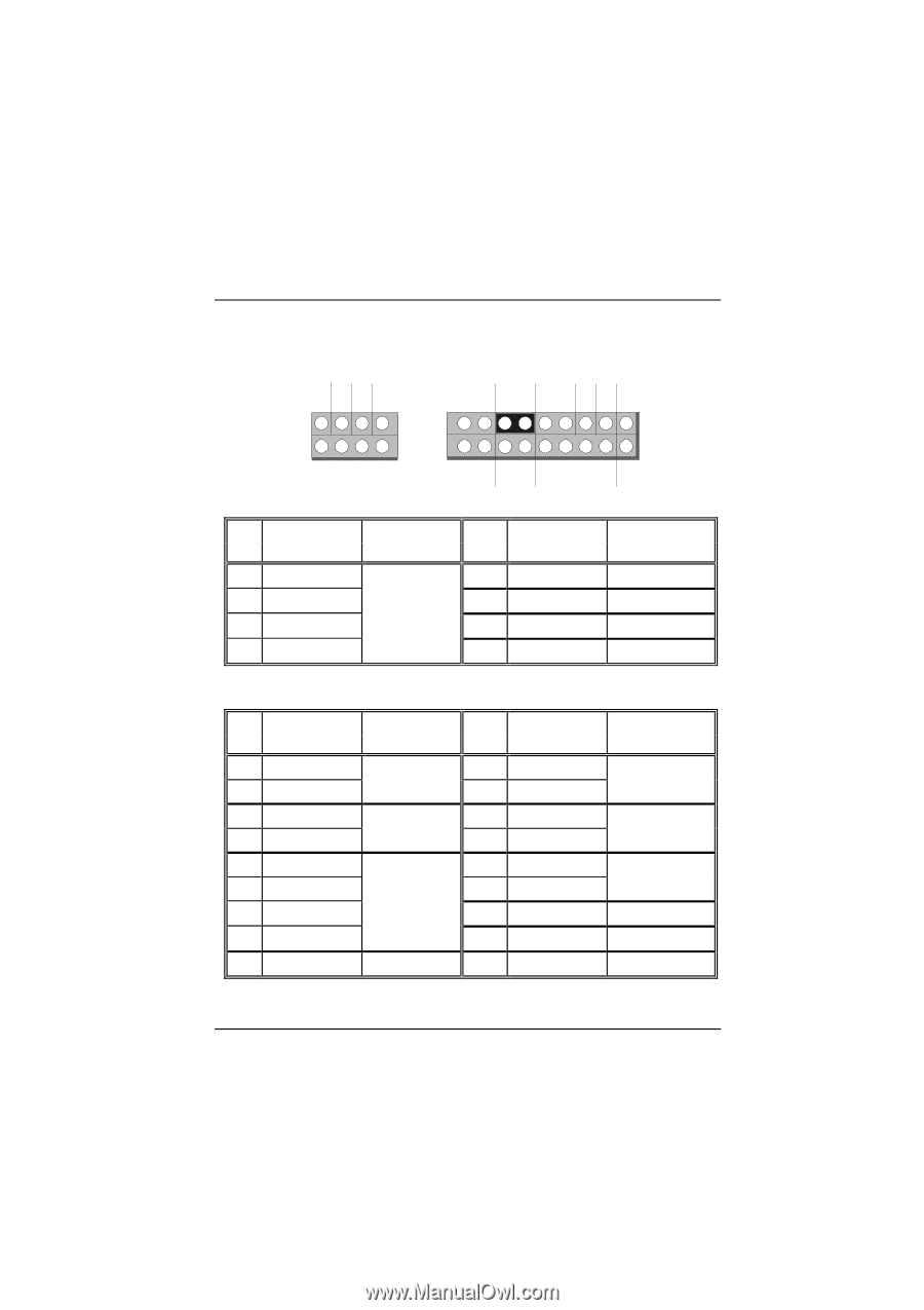
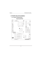
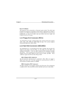
Chapter 1 Motherboard Description 1.3.1 Front Panel Connectors (JPANEL1 / JPANEL2) JPANEL1 JPANEL2 V G NC PWR-LED PWR-LED PWR 2 82 1 71 SPK HLED RST SLP NC V NC 18 17 IR NC JPANEL1 Pin Assignment No. 1 +5V 3 No Connection 5 Ground 7 Speaker Function Speaker Connector Pin Assignment No. Function 2 +5V VCC 4 Ground Ground 6 No Connection No Connection 8 Power LED(-) PWR LED JPANEL2 Pin Assignment Function No. Pin Assignment No. Function 1 HDD LED (+) 3 HDD LED (-) 5 Ground 7 Reset Control Hard Drive LED Reset Button 2 Power LED (-) 4 Power LED (+) PWR LED 6 Power Button ATX Power 8 Ground Button 9 +5V 11 Ir-In 13 Ground 15 Ir-Out IrDA Connector 10 Sleep Control 12 Ground SLP Button 14 No Connection No Connection 16 +5V VCC 17 No Connection No Connection 18 No Connection No Connection 1-8
-
 1
1 -
2
-
3
-
4
-
5
-
6
-
7
-
 8
8 -
 9
9 -
 10
10 -
 11
11 -
 12
12 -
 13
13 -
 14
14 -
 15
15 -
 16
16 -
 17
17 -
 18
18 -
19
-
20
-
21
-
22
-
23
-
24
-
25
-
26
-
27
-
28
-
29
-
30
-
31
-
32
-
33
-
34
-
35
-
36
-
37
-
38
-
39
-
40
-
41
-
42
-
43
-
44
-
45
-
46
-
47
-
48
-
49
-
50
-
51
-
52
-
53
-
54
-
55
-
56
-
57
-
58
-
59
-
60
-
61
-
62
-
63
-
64
-
65
-
66
-
67
-
68
-
69
-
70
-
71
-
72
-
73
-
74
-
75
-
76
-
77
-
78
-
79
-
80
-
81
-
82
-
83
 |
 |