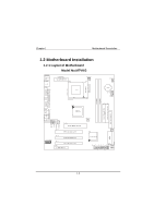
Biostar M7VKG M7VKG user's manual - Page 14
Hard Drive LED Connector, Power LED Connector - driver
 |
View all Biostar M7VKG manuals
Add to My Manuals
Save this manual to your list of manuals |
Page 14 highlights
Chapter 1 Motherboard Description Speaker Connector An offboard speaker can be installed on the motherboard as a manufacturing option. An offboard speaker can be connected to the motherboard at the front panel connector. The speaker (onboard or offboard) provides error beep code information during the Power On Self-Test when the computer cannot use the video interface. The speaker is not connected to the audio subsystem and does not receive output from the audio subsystem. Reset Button This connector can be connected to a momentary SPST type switch that is normally open. When the switch is closed, the motherboard resets and runs the POST. Power LED Connector This connector can be connected to an LED that will light when the computer is powered on. Hard Drive LED Connector This connector can be connected to an LED to provide a visual indicator that data is being read from or written to a hard drive. For the LED to function properly, an IDE drive must be connected to the onboard hard drive controller. Infrared Connector After the IrDA interface is configured, files can be transferred from or to portable devices such as laptops, PDAs, and printers using application software. Sleep Button When APM is enabled in the system BIOS, and the operating system's APM driver is loaded, the system can enter sleep (standby) mode in one of the following ways: • Optional front panel SMI button • Prolonged system inactivity using the BIOS inactivity timer feature The 2-pin header located on the front panel I/O connector supports a front panel SMI switch, which must be a momentary SPST type that is normally open. Closing the SMI switch sends a System Management Interrupt (SMI) to the processor, which immediately goes into System Management Mode (SMM).While the computer is in sleep mode it is fully capable of responding to and servicing external interrupts (such as an incoming fax) even though the monitor turns on only if a keyboard or mouse interrupt occurs. To reactivate or resume the system, the SMI switch must be pressed again, or the keyboard or mouse must be used. 1-9
-
 1
1 -
2
-
3
-
4
-
5
-
6
-
7
-
8
-
 9
9 -
 10
10 -
 11
11 -
 12
12 -
 13
13 -
 14
14 -
 15
15 -
 16
16 -
 17
17 -
 18
18 -
 19
19 -
20
-
21
-
22
-
23
-
24
-
25
-
26
-
27
-
28
-
29
-
30
-
31
-
32
-
33
-
34
-
35
-
36
-
37
-
38
-
39
-
40
-
41
-
42
-
43
-
44
-
45
-
46
-
47
-
48
-
49
-
50
-
51
-
52
-
53
-
54
-
55
-
56
-
57
-
58
-
59
-
60
-
61
-
62
-
63
-
64
-
65
-
66
-
67
-
68
-
69
-
70
-
71
-
72
-
73
-
74
-
75
-
76
-
77
-
78
-
79
-
80
-
81
-
82
-
83
 |
 |
