Biostar M7VKG M7VKG user's manual - Page 15
Floppy Disk Connector (FDD1), 1.3.3 Hard Disk Connectors (IDE1/IDE2), Power On Button - bios
 |
View all Biostar M7VKG manuals
Add to My Manuals
Save this manual to your list of manuals |
Page 15 highlights
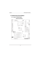
Chapter 1 Motherboard Description Power On Button This connector can be connected to a front panel power switch. The switch must pull the Power Button pin to ground for at least 50 ms to signal the power supply to switch on or off. (The time requirement is due to internal debounce circuitry on the motherboard). At least two seconds must pass before the power supply will recognize another on/off signal. 1.3.2 Floppy Disk Connector (FDD1) The motherboard provides a standard floppy disk connector (FDC) that supports 360K, 720K, 1.2M, 1.44M and 2.88M floppy disk types. This connector supports the provided floppy drive ribbon cables. 1.3.3 Hard Disk Connectors (IDE1/IDE2) The motherboard has a 32-bit Enhanced PCI IDE Controller that provides PIO Mode 0~4, Bus Master, and Ultra DMA / 33, Ultra DMA / 66, Ultra DMA / 100 (optional) functionality. It has two HDD connectors IDE1 (primary) and IDE2 (secondary). You can connect up to four hard disk drives, a CD-ROM, a 120MB Floppy (reserved for future BIOS) and other devices to IDE1 and IDE2. These connectors support the IDE hard disk cable provided. • IDE1 (Primary IDE Connector) The first hard drive should always be connected to IDE1. IDE1 can connect a Master and a Slave drive. You must configure the second hard drive on IDE1 to Slave mode by setting the jumper accordingly. • IDE2 (Secondary IDE Connector) The IDE2 controller can also support a Master and a Slave drive. The configuration is similar to IDE1. The second drive on this controller must be set to slave mode. 1-10
-
 1
1 -
2
-
3
-
4
-
5
-
6
-
7
-
8
-
9
-
 10
10 -
 11
11 -
 12
12 -
 13
13 -
 14
14 -
 15
15 -
 16
16 -
 17
17 -
 18
18 -
 19
19 -
 20
20 -
21
-
22
-
23
-
24
-
25
-
26
-
27
-
28
-
29
-
30
-
31
-
32
-
33
-
34
-
35
-
36
-
37
-
38
-
39
-
40
-
41
-
42
-
43
-
44
-
45
-
46
-
47
-
48
-
49
-
50
-
51
-
52
-
53
-
54
-
55
-
56
-
57
-
58
-
59
-
60
-
61
-
62
-
63
-
64
-
65
-
66
-
67
-
68
-
69
-
70
-
71
-
72
-
73
-
74
-
75
-
76
-
77
-
78
-
79
-
80
-
81
-
82
-
83
 |
 |