Bosch WTMC5530UC Operating, Care, Installation - Page 10
Warning, Caution - rating
 |
View all Bosch WTMC5530UC manuals
Add to My Manuals
Save this manual to your list of manuals |
Page 10 highlights
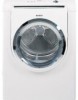
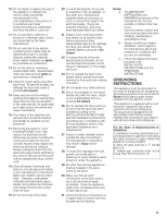
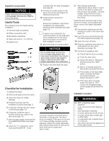
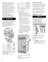
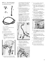
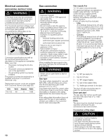
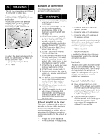
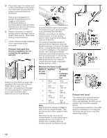
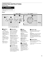
Electrical connection GROUNDING INSTRUCTIONS d WARNING The dryer must only be connected to an individual branch circuit via a socket which has been properly installed and grounded. The household electrical voltage must correspond to the voltage specification on the dryer (rating plate). You will find the rating plate on the inside of the front panel. Connection specifications as well as the electrical requirements are stipulated on the appliance nameplate. Make sure that: - the power cord plug fits into the socket. - the power cord is acceptable for use in this application. - the grounding system is properly installed. The power cord may be replaced by a qualified technician or a licensed electrician only. Replacement power cords are available from Customer Service (see page 26). Volts Hertz Amperes Watts 110-120 60 9 1080 10 Gas connection d WARNING Explosion hazard! Use a new AGA or CSA approved gas supply line. Install a shutĆoff valve. Securely tighten all gas connections. Do not crush or kink the gas line. Have a qualified person make sure gas pressure does not exceed 14 in. W.C./ 3.49 kPa/ 0.506 psig. (Natural Gas and Propane). Example of a qualified person include: - licensed heating personnel, - authorized gas supplier personnel, - authorized service personnel. Failure to do so can result in explosion or fire. Risk of death or injury! All gas line connections must be tested for leaks prior to appliance operation. Apply soapy water to gas line connections and check for formation of new bubbles. Bubbles indicate a leak! When installing the gas supply to the gas dryer inlet pipe, do not exceed 26 ft-lb (35 Nm). d WARNING Never use an open flame to test for gas leaks. Gas type This dryer when equipped for use with NATURAL GAS will employ an orifice size 46 and will have a gas outlet pressure of 3.5 in. W.C. Your dryer must have the correct valve for the type of gas in your home. Valve information is located on the rating plate behind the door below the port hole. If the ratingĆplate information does not agree with the type of gas available, contact your dealer or our customer service team (see page 26). Gas supply line 13le//n28""gtaI.hpDsp.urponipvdeeedris2tur0ebfcitno(g6m.is1mamecn)cdiefepldotc.aablle for codes and gas supplier permit. Mtapusptiningc, liumdme e1d/8ia" tNelPyTuppslutgregaemd of the gas connection. A shut off valve must be included: - USA: An individual manual shutĆoff valve must be installed within 6 ft (1.8 m) of the dryer in accordance with the National Fuel Gas Code, ANSI Z223.1/NFPA 54. - Canada: An individual manual shutĆoff valve must be installed in accordance with the B149, Installation Codes, CAN/CSA B149.1 and CAN/CSA B149.2. It is recommended that an individual manual shutĆoff valve be installed within 6 ft (1.8 m) of the dryer. 5 43 2 1 1 1 ć 1/2" NPT gas supply line 2 ć Gas shutĆoff valve 3 ć 1/8" NPT plugged tapping 4 ć 3/8" pipe to flare adapter fitting 5 ć 3/8" flexible gas connector (to the dryer) The shutĆoff valve should be easy to reach for opening and closing. Dryer gas pipe The gas pipe that comes out through the rear of the pipe thread. dryer has a 3/8" male Note: The dryer must be checked for proper operation whenever the gas connections have been broken. Connection of the dryer d CAUTION Connection must be made by a qualified technician. The dryer must be disconnected from the gas supply piping system during pressure testing. When using for the first time make sure that there is no air in the piping system.
-
 1
1 -
2
-
3
-
4
-
 5
5 -
 6
6 -
 7
7 -
 8
8 -
 9
9 -
 10
10 -
 11
11 -
 12
12 -
 13
13 -
 14
14 -
 15
15 -
16
-
17
-
18
-
19
-
20
-
21
-
22
-
23
-
24
-
25
-
26
-
27
-
28
-
29
-
30
-
31
-
32
-
33
-
34
-
35
-
36
-
37
-
38
-
39
-
40
-
41
-
42
-
43
-
44
-
45
-
46
-
47
-
48
-
49
-
50
-
51
-
52
-
53
-
54
-
55
-
56
-
57
-
58
-
59
-
60
-
61
-
62
-
63
-
64
-
65
-
66
-
67
-
68
-
69
-
70
-
71
-
72
-
73
-
74
-
75
-
76
-
77
-
78
-
79
-
80
-
81
-
82
-
83
-
84
-
85
-
86
-
87
-
88
 |
 |