Brother International PT-9600 Service Manual - Page 19
Roller Holder ASSY Setting & Retracting Mechanism
 |
UPC - 012502602774
View all Brother International PT-9600 manuals
Add to My Manuals
Save this manual to your list of manuals |
Page 19 highlights
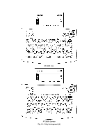
2.1.2 Roller Holder ASSY Setting & Retracting Mechanism This mechanism consists of the release lever, roller release rod, and roller holder/head assy. The roller holder assy incorporates the platen holder and the sub roller holder. These holders support the platen and the tape feed sub roller so that they can move perpendicularly to the thermal head and the tape feed roller, respectively. The platen is pressed perpendicularly against the thermal head under a uniform load regardless of the thickness of the tape, so that the tape is fed. Closing the cassette cover pushes down the release lever which moves the roller release rod to the left (when viewed from the front of the machine). This pivots the roller holder assy around the shaft secured on the thermal head assy so as to press the roller holder assy against the thermal head. The platen is pressed perpendicularly against the thermal head with the tape and ink ribbon (only the tape when using AV labels cassettes or stamp tape cassettes) sandwiched inbetween under a uniform load by the platen spring. At the same time, the platen gear becomes engaged with the platen idle gear. Also, the tape feed sub roller is pressed perpendicularly against the tape feed roller built in the tape cassette with the tape (and base paper when using laminated tape cassettes or stamp tape cassettes) sandwiched inbetween under a uniform load by the sub roller holder springs. At the same time, the sub roller gear becomes engaged with the tape feed roller. Opening the cassette cover causes the release lever spring to slide the roller release rod in the direction of the arrow. This retracts the roller holder assy from the thermal head, providing you with enough space to replace the tape cassette. Tape cassette Adhesive base tape Platen idle gear Laminated tape Tape feed roller Platen Tape feed sub roller Ink ribbon Roller holder shaft Roller holder ASSY Roller release rod Sub roller gear Release lever Thermal head Platen roller Sub roller Platen gear Sub roller spring Platen spring Roller holder Fig. 2.1-2 Roller Holder ASSY Setting & Retracting Mechanism II-3
-
 1
1 -
2
-
3
-
4
-
5
-
6
-
7
-
8
-
9
-
10
-
11
-
12
-
13
-
 14
14 -
 15
15 -
 16
16 -
 17
17 -
 18
18 -
 19
19 -
 20
20 -
 21
21 -
 22
22 -
 23
23 -
 24
24 -
25
-
26
-
27
-
28
-
29
-
30
-
31
-
32
-
33
-
34
-
35
-
36
-
37
-
38
-
39
-
40
-
41
-
42
-
43
-
44
-
45
-
46
-
47
-
48
-
49
-
50
-
51
-
52
-
53
-
54
-
55
-
56
-
57
-
58
-
59
-
60
-
61
-
62
-
63
-
64
-
65
-
66
-
67
-
68
-
69
-
70
-
71
-
72
-
73
-
74
-
75
-
76
-
77
-
78
-
79
-
80
-
81
-
82
-
83
-
84
-
85
-
86
-
87
-
88
-
89
-
90
-
91
-
92
-
93
-
94
-
95
-
96
-
97
-
98
-
99
-
100
-
101
-
102
-
103
-
104
-
105
-
106
-
107
-
108
-
109
-
110
-
111
-
112
-
113
-
114
-
115
-
116
-
117
-
118
-
119
-
120
-
121
-
122
-
123
-
124
-
125
-
126
-
127
-
128
-
129
-
130
-
131
-
132
-
133
-
134
-
135
-
136
-
137
-
138
-
139
-
140
-
141
-
142
-
143
-
144
-
145
-
146
-
147
-
148
-
149
-
150
-
151
-
152
-
153
-
154
-
155
-
156
-
157
-
158
-
159
-
160
-
161
-
162
-
163
-
164
-
165
 |
 |
