Canon 1692B002 Service Manual - Page 100
Points to Note on Disassembly and Reassembly
 |
View all Canon 1692B002 manuals
Add to My Manuals
Save this manual to your list of manuals |
Page 100 highlights
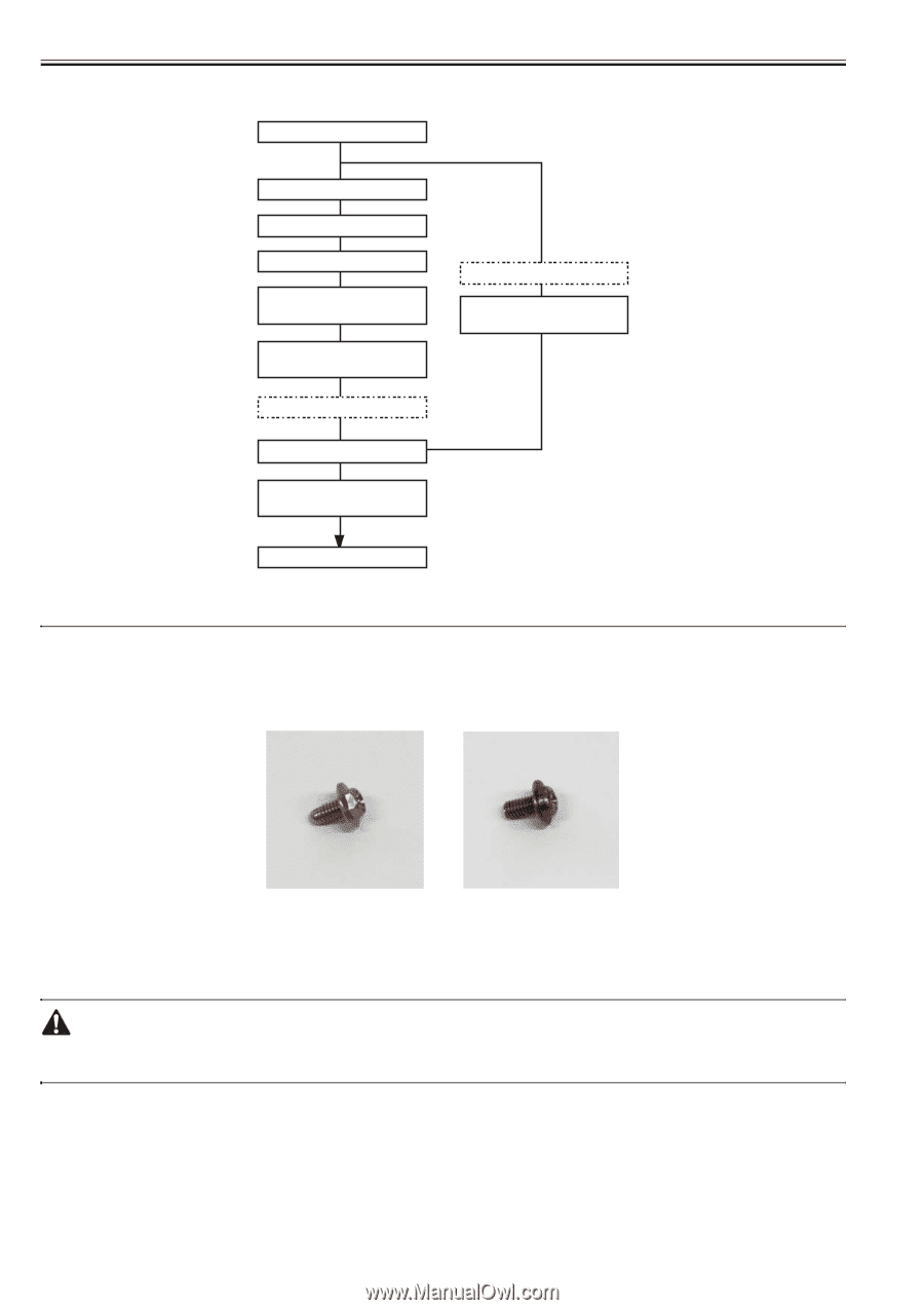
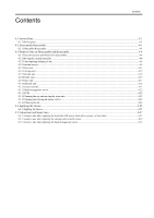
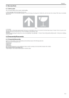
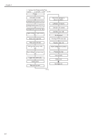
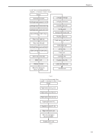
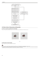
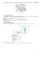
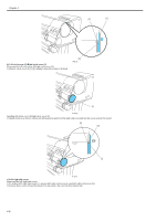
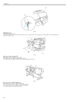
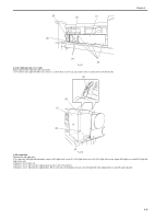
Chapter 4 4. Ink Tank unit Disassembly Flow c: Connector h: Hook s: Screw Printer Right circle cover (L) (h1) Right circle cover (S) (h1) Right side covers (s3, h2) Left/right tank cover units (s3) Move the carriage to above the platen Manual ink drain Drain the ink in subtanks Remove the left/right ink tube joints Automatic ink drain Left/right tank cover units (s3) Ink tank unit(c5, s2) F-4-5 4.3 Points to Note on Disassembly and Reassembly 4.3.1 Note on locations prohibited from disassembly 0012-6514 Points where disassembly is forbidden because they are not accessible to a market adjustment are marked by red screws. F-4-6 4.3.2 Moving the carriage manually 0014-8950 When moving the carriage, hold it by handle [1] shown below. Move the carriage as required during assembly and disassembly to prevent the carriage from contacting the parts to be removed. You cannot move the carriage when capping has been performed. Refer to DISASSEMBLY/REASSEMBLY > Points to Notes on Disassembly and Reassembly > Opening the caps and moving the wiper unit to remove the caps, and then move the carriage. 4-4
-
 1
1 -
2
-
3
-
4
-
5
-
6
-
7
-
8
-
9
-
10
-
11
-
12
-
13
-
14
-
15
-
16
-
17
-
18
-
19
-
20
-
21
-
22
-
23
-
24
-
25
-
26
-
27
-
28
-
29
-
30
-
31
-
32
-
33
-
34
-
35
-
36
-
37
-
38
-
39
-
40
-
41
-
42
-
43
-
44
-
45
-
46
-
47
-
48
-
49
-
50
-
51
-
52
-
53
-
54
-
55
-
56
-
57
-
58
-
59
-
60
-
61
-
62
-
63
-
64
-
65
-
66
-
67
-
68
-
69
-
70
-
71
-
72
-
73
-
74
-
75
-
76
-
77
-
78
-
79
-
80
-
81
-
82
-
83
-
84
-
85
-
86
-
87
-
88
-
89
-
90
-
91
-
92
-
93
-
94
-
 95
95 -
 96
96 -
 97
97 -
 98
98 -
 99
99 -
 100
100 -
 101
101 -
 102
102 -
 103
103 -
 104
104 -
 105
105 -
106
-
107
-
108
-
109
-
110
-
111
-
112
-
113
-
114
-
115
-
116
-
117
-
118
-
119
-
120
-
121
-
122
-
123
-
124
-
125
-
126
-
127
-
128
-
129
-
130
-
131
-
132
-
133
-
134
-
135
-
136
-
137
-
138
-
139
-
140
-
141
-
142
-
143
-
144
-
145
-
146
-
147
-
148
-
149
-
150
-
151
-
152
-
153
-
154
-
155
-
156
-
157
-
158
-
159
-
160
-
161
-
162
-
163
-
164
-
165
-
166
-
167
-
168
-
169
-
170
-
171
-
172
-
173
-
174
-
175
-
176
-
177
-
178
-
179
-
180
-
181
-
182
-
183
-
184
-
185
-
186
-
187
-
188
-
189
-
190
-
191
-
192
-
193
-
194
-
195
-
196
-
197
-
198
-
199
-
200
 |
 |