Canon 1692B002 Service Manual - Page 147
Location of Connectors and Pin Arrangement
 |
View all Canon 1692B002 manuals
Add to My Manuals
Save this manual to your list of manuals |
Page 147 highlights
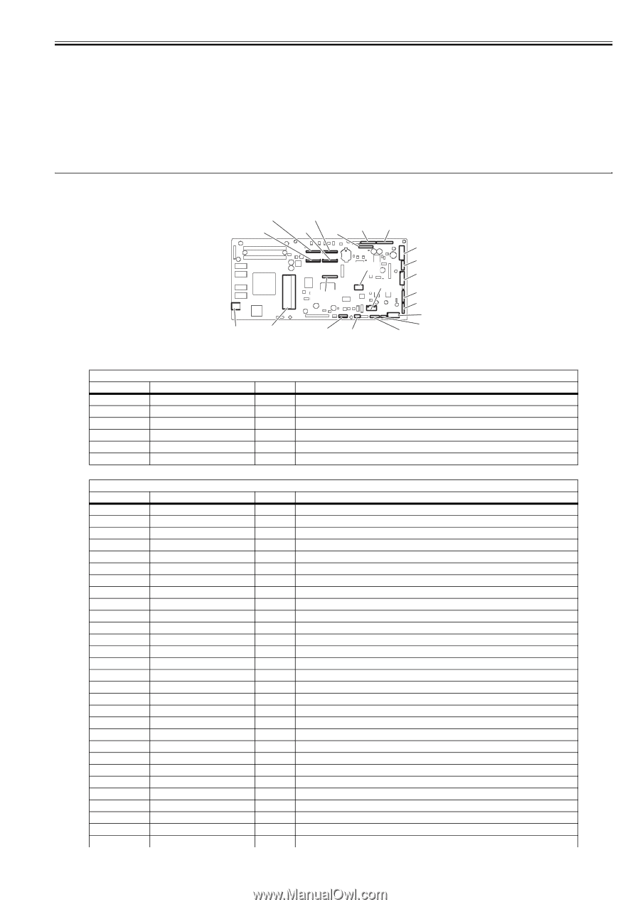
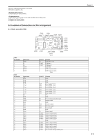
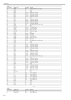
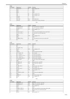
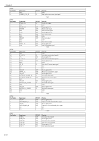
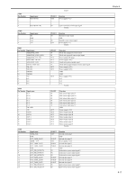
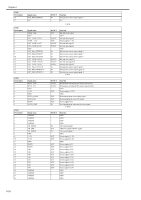
The RTC of the main controller is not found. The battery capacity is low. Lithium battery or main controller 1) Start up the printer in the service mode, and then turn off the power. 2) Replace the lithium battery. 3) Replace the main controller 6.2 Location of Connectors and Pin Arrangement 6.2.1 Main controller PCB J1001 Pin Number 1 2 3 4 5 6 Signal name VBUS DD+ AGND FGND FGND J1101 Pin Number 1 2 3 4 5 6 7 8 9 10 11 12 13 14 15 16 17 18 19 20 21 22 23 24 25 26 27 28 29 Signal name GND GND GND +3.3V +3.3V +3.3V +3.3V +3.3V +3.3V N.C. GND /PME /INTA GND /RST CLK /GNT GND /REQ AD31 AD30 AD29 AD28 GND AD27 AD26 AD25 AD24 /CBE3 J3501 J3601 J3502 J3602 J3202 J3201 J3003 J1001 J1101 J1801 J3150 J2801 J2501 J3401 J3001 J2601 J2402 J2701 J3301 J3002 J2702 J2502 F-6-1 T-6-1 IN/OUT IN IN/OUT IN/OUT - Function USB VBUS(+5V) USB data(-) USB data(+) USB GND GND (Connector shell) GND (Connector shell) T-6-2 IN/OUT OUT OUT OUT OUT OUT OUT IN IN OUT OUT OUT IN IN/OUT IN/OUT IN/OUT IN/OUT IN/OUT IN/OUT IN/OUT IN/OUT IN/OUT Function GND GND GND power supply(+3.3V) power supply(+3.3V) power supply(+3.3V) power supply(+3.3V) power supply(+3.3V) power supply(+3.3V) N.C. GND Power management enable signal Interrupt signal GND PCI Reset signal PCI Clock signal Ground signal GND Request signal Address and data signal Address and data signal Address and data signal Address and data signal GND Address and data signal Address and data signal Address and data signal Address and data signal Bus command and byte enable signal Chapter 6 0014-9207 6-13
-
 1
1 -
2
-
3
-
4
-
5
-
6
-
7
-
8
-
9
-
10
-
11
-
12
-
13
-
14
-
15
-
16
-
17
-
18
-
19
-
20
-
21
-
22
-
23
-
24
-
25
-
26
-
27
-
28
-
29
-
30
-
31
-
32
-
33
-
34
-
35
-
36
-
37
-
38
-
39
-
40
-
41
-
42
-
43
-
44
-
45
-
46
-
47
-
48
-
49
-
50
-
51
-
52
-
53
-
54
-
55
-
56
-
57
-
58
-
59
-
60
-
61
-
62
-
63
-
64
-
65
-
66
-
67
-
68
-
69
-
70
-
71
-
72
-
73
-
74
-
75
-
76
-
77
-
78
-
79
-
80
-
81
-
82
-
83
-
84
-
85
-
86
-
87
-
88
-
89
-
90
-
91
-
92
-
93
-
94
-
95
-
96
-
97
-
98
-
99
-
100
-
101
-
102
-
103
-
104
-
105
-
106
-
107
-
108
-
109
-
110
-
111
-
112
-
113
-
114
-
115
-
116
-
117
-
118
-
119
-
120
-
121
-
122
-
123
-
124
-
125
-
126
-
127
-
128
-
129
-
130
-
131
-
132
-
133
-
134
-
135
-
136
-
137
-
138
-
139
-
140
-
141
-
 142
142 -
 143
143 -
 144
144 -
 145
145 -
 146
146 -
 147
147 -
 148
148 -
 149
149 -
 150
150 -
 151
151 -
 152
152 -
153
-
154
-
155
-
156
-
157
-
158
-
159
-
160
-
161
-
162
-
163
-
164
-
165
-
166
-
167
-
168
-
169
-
170
-
171
-
172
-
173
-
174
-
175
-
176
-
177
-
178
-
179
-
180
-
181
-
182
-
183
-
184
-
185
-
186
-
187
-
188
-
189
-
190
-
191
-
192
-
193
-
194
-
195
-
196
-
197
-
198
-
199
-
200
 |
 |