Canon 1692B002 Service Manual - Page 99
Ink Tube Unit Disassembly Flow
 |
View all Canon 1692B002 manuals
Add to My Manuals
Save this manual to your list of manuals |
Page 99 highlights
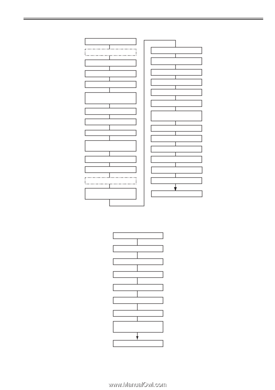
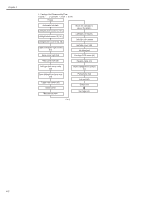
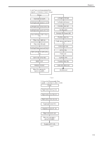
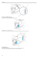
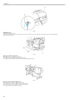
2. Ink Tube Unit Disassembly Flow c: Connector h: Hook s: Screw Printer Automatic ink drain Left/right circle covers (L) (h1) Left/right circle covers (S) (h1) Left/right side covers (s3, h2) Upper left/upper right covers (h1) Rear cover right (s4) Rear cover left (s2) Left/right tank cover unit (s3) Open left/right ink tank units (s4) Upper rear cover (s5) Upper cover Manual ink drain Move the carriage to above the platen Left/right printhead Left/right joint bases Ink tube cover (s2) Ink tube joint Carriage PCB cover (s4) Flexible cable (c3) Head management sensor (s1) Pulley base (s3) Lift unit (s5) Cutter unit Carriage unit Flexible cable (c5) Cable fixer base (s3) Ink tube unit F-4-3 3. Purge Unit Disassembly Flow c: Connector h: Hook s: Screw Printer Right circle cover (L) (h1) Right circle cover (S) (h1) Right side covers (s3, h2) Upper right cover (h1) Operation panel (h1, c2) Right front cover (s2) Move the carriage to above the platen Purge unit (c1, s3) F-4-4 Chapter 4 4-3
-
 1
1 -
2
-
3
-
4
-
5
-
6
-
7
-
8
-
9
-
10
-
11
-
12
-
13
-
14
-
15
-
16
-
17
-
18
-
19
-
20
-
21
-
22
-
23
-
24
-
25
-
26
-
27
-
28
-
29
-
30
-
31
-
32
-
33
-
34
-
35
-
36
-
37
-
38
-
39
-
40
-
41
-
42
-
43
-
44
-
45
-
46
-
47
-
48
-
49
-
50
-
51
-
52
-
53
-
54
-
55
-
56
-
57
-
58
-
59
-
60
-
61
-
62
-
63
-
64
-
65
-
66
-
67
-
68
-
69
-
70
-
71
-
72
-
73
-
74
-
75
-
76
-
77
-
78
-
79
-
80
-
81
-
82
-
83
-
84
-
85
-
86
-
87
-
88
-
89
-
90
-
91
-
92
-
93
-
 94
94 -
 95
95 -
 96
96 -
 97
97 -
 98
98 -
 99
99 -
 100
100 -
 101
101 -
 102
102 -
 103
103 -
 104
104 -
105
-
106
-
107
-
108
-
109
-
110
-
111
-
112
-
113
-
114
-
115
-
116
-
117
-
118
-
119
-
120
-
121
-
122
-
123
-
124
-
125
-
126
-
127
-
128
-
129
-
130
-
131
-
132
-
133
-
134
-
135
-
136
-
137
-
138
-
139
-
140
-
141
-
142
-
143
-
144
-
145
-
146
-
147
-
148
-
149
-
150
-
151
-
152
-
153
-
154
-
155
-
156
-
157
-
158
-
159
-
160
-
161
-
162
-
163
-
164
-
165
-
166
-
167
-
168
-
169
-
170
-
171
-
172
-
173
-
174
-
175
-
176
-
177
-
178
-
179
-
180
-
181
-
182
-
183
-
184
-
185
-
186
-
187
-
188
-
189
-
190
-
191
-
192
-
193
-
194
-
195
-
196
-
197
-
198
-
199
-
200
 |
 |