Canon EOS C200 EOS C200 EOS C200B Instruction Manual - Page 29
Using the UN-5 Unit Cable, To attach the LCD monitor to the camera
 |
View all Canon EOS C200 manuals
Add to My Manuals
Save this manual to your list of manuals |
Page 29 highlights
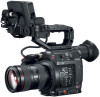
Preparing the Handle Unit and LCD Monitor 3 Align the LCD attachment unit mount to the handle unit's front accessory mount and then use the wrench to tighten the LCD attachment unit lock screw (ቤ). 4 Rotate the LCD monitor mount 180° toward the handle unit (ብ). ብ 5 Using the UN-5 Unit Cable2, connect the camera's ቤ VIDEO terminal to the LCD monitor's VIDEO terminal (ቦ). 29 ቦ 2 Supplied accessory for the C200; optional accessory for the ቤ C200B. • Align the Í marks on the cables' plugs and terminals. • Put the cable though the LCD attachment unit's cable clamp (ቧ). If necessary, adjust the position of the cable so that it does not get in the way of the lens. NOTES • Depending on the situation, the screws may become loose. If necessary, use the hex wrench (for 0.64 cm, 1/4" screws) to tighten them. ቦ ቧ To attach the LCD monitor to the camera 1 Set the Q switch to OFF. • If the handle unit is attached to the camera, remove it. 2 Remove LCD attachment unit base 2 (ባ). • Use a hex wrench (for 0.64 cm, 1/4" screws)1. 1 Supplied with the HDU-2. 3 Attach LCD attachment unit base 2 to the camera (ቤ). • Use the hex wrench to secure it firmly with the hex socket head bolt. 4 Rotate LCD attachment unit pivot B 90° toward the SD card slots and then rotate the LCD monitor mount 180° toward the tape measure hook (ብ). ቤ ባ ብ
-
 1
1 -
2
-
3
-
4
-
5
-
6
-
7
-
8
-
9
-
10
-
11
-
12
-
13
-
14
-
15
-
16
-
17
-
18
-
19
-
20
-
21
-
22
-
23
-
 24
24 -
 25
25 -
 26
26 -
 27
27 -
 28
28 -
 29
29 -
 30
30 -
 31
31 -
 32
32 -
 33
33 -
 34
34 -
35
-
36
-
37
-
38
-
39
-
40
-
41
-
42
-
43
-
44
-
45
-
46
-
47
-
48
-
49
-
50
-
51
-
52
-
53
-
54
-
55
-
56
-
57
-
58
-
59
-
60
-
61
-
62
-
63
-
64
-
65
-
66
-
67
-
68
-
69
-
70
-
71
-
72
-
73
-
74
-
75
-
76
-
77
-
78
-
79
-
80
-
81
-
82
-
83
-
84
-
85
-
86
-
87
-
88
-
89
-
90
-
91
-
92
-
93
-
94
-
95
-
96
-
97
-
98
-
99
-
100
-
101
-
102
-
103
-
104
-
105
-
106
-
107
-
108
-
109
-
110
-
111
-
112
-
113
-
114
-
115
-
116
-
117
-
118
-
119
-
120
-
121
-
122
-
123
-
124
-
125
-
126
-
127
-
128
-
129
-
130
-
131
-
132
-
133
-
134
-
135
-
136
-
137
-
138
-
139
-
140
-
141
-
142
-
143
-
144
-
145
-
146
-
147
-
148
-
149
-
150
-
151
-
152
-
153
-
154
-
155
-
156
-
157
-
158
-
159
-
160
-
161
-
162
-
163
-
164
-
165
-
166
-
167
-
168
-
169
-
170
-
171
-
172
-
173
-
174
-
175
-
176
-
177
-
178
-
179
-
180
-
181
-
182
-
183
-
184
-
185
-
186
-
187
-
188
-
189
-
190
-
191
-
192
-
193
-
194
-
195
-
196
-
197
-
198
-
199
-
200
-
201
-
202
-
203
-
204
-
205
-
206
-
207
-
208
-
209
-
210
-
211
-
212
-
213
-
214
-
215
-
216
-
217
-
218
-
219
-
220
-
221
-
222
-
223
-
224
-
225
-
226
-
227
-
228
-
229
-
230
-
231
-
232
-
233
-
234
-
235
-
236
-
237
 |
 |
