Canon PC740 Service Manual - Page 103
Detecting, Errors, Composite, Power, Supply, Protection, Mechanism, Circuit
 |
View all Canon PC740 manuals
Add to My Manuals
Save this manual to your list of manuals |
Page 103 highlights
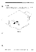
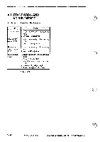
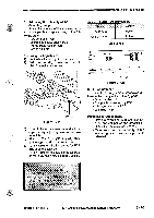
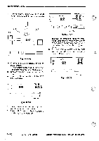
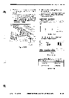
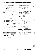
OPERATIONS AND TIMINGMil C. Detecting Errors by the Composite Power Supply PCB The copier's composite power supply PCB is equipped with a microprocessor (Q900) which serves to run a self diagnosis program to check the output from each power supply and its communications with the DC controller PCB. When an error occurs, the microprocessor communicates with the DC controller PCB so that the results of self diagnosis may be indicated in the display on the control panel. 1. Overcurrent (low voltage) If the composite power supply PCB finds an error in a DC load, it will turn off the relay (RL601) to cut off the AC input. 2. Error in the Control Value (high voltage) If the composite power supply PCB finds that the difference between the setting and the actual value of either of the following voltages is not as specified, it will indicate `E064' on the control panel. • primary DC bias • developing DC bias • transfer bias 3. Error in the Control Value (low voltage) If the composite power supply PCB finds that the difference between the setting for +24 V of the DC output and the control value is not as specified, it will indicate 'E803' on the display of the control panel. 4. Error in the Communication with the DC Controller If the DC controller PCB finds an error in the communication between the DC controller PCB and the composite power supply PCB, `E240' will appear in the display of the control panel for about 4 sec; thereafter, the relay (RL601) is turned off to cut off the AC input. D. Protection Mechanism of the Power Supply Circuit The composite power supply PCB has an overcurrent detection function which turns on to stop the output. When the output has stopped, it may be reset by opening the copier's top unit, correcting the load, and turning on the power switch. The built-in fuse (FU102), however, will blow if loads are repeatedly short circuited and reset. COPYRIGHT © 1994 CANON INC. CANON PC72074011501170 REY.0 AUG.1994 PRINTED IN JAPAN (await AU JAPON) 3 - 63
-
 1
1 -
2
-
3
-
4
-
5
-
6
-
7
-
8
-
9
-
10
-
11
-
12
-
13
-
14
-
15
-
16
-
17
-
18
-
19
-
20
-
21
-
22
-
23
-
24
-
25
-
26
-
27
-
28
-
29
-
30
-
31
-
32
-
33
-
34
-
35
-
36
-
37
-
38
-
39
-
40
-
41
-
42
-
43
-
44
-
45
-
46
-
47
-
48
-
49
-
50
-
51
-
52
-
53
-
54
-
55
-
56
-
57
-
58
-
59
-
60
-
61
-
62
-
63
-
64
-
65
-
66
-
67
-
68
-
69
-
70
-
71
-
72
-
73
-
74
-
75
-
76
-
77
-
78
-
79
-
80
-
81
-
82
-
83
-
84
-
85
-
86
-
87
-
88
-
89
-
90
-
91
-
92
-
93
-
94
-
95
-
96
-
97
-
 98
98 -
 99
99 -
 100
100 -
 101
101 -
 102
102 -
 103
103 -
 104
104 -
 105
105 -
 106
106 -
 107
107 -
 108
108 -
109
-
110
-
111
-
112
-
113
-
114
-
115
-
116
-
117
-
118
-
119
-
120
-
121
-
122
-
123
-
124
-
125
-
126
-
127
-
128
-
129
-
130
-
131
-
132
-
133
-
134
-
135
-
136
-
137
-
138
-
139
-
140
-
141
-
142
-
143
-
144
-
145
-
146
-
147
-
148
-
149
-
150
-
151
-
152
-
153
-
154
-
155
-
156
-
157
-
158
-
159
-
160
-
161
-
162
-
163
-
164
-
165
-
166
-
167
-
168
-
169
-
170
-
171
-
172
-
173
-
174
-
175
-
176
-
177
-
178
-
179
-
180
-
181
-
182
-
183
-
184
-
185
-
186
-
187
-
188
-
189
-
190
-
191
-
192
-
193
-
194
-
195
-
196
-
197
-
198
-
199
-
200
 |
 |
