Canon PC740 Service Manual - Page 51
Exposure, System
 |
View all Canon PC740 manuals
Add to My Manuals
Save this manual to your list of manuals |
Page 51 highlights
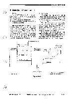
OPERATIONS AND TIMINGM II. EXPOSURE SYSTEM A. Varying the Reproduction Ratio The reproduction ratio in the direction of the drum axis is varied by the lens drive system and that around the drum, by the scanner drive system. The lens drive system holds a lens array and changes the location of the lens and the optical path length as shown in Figure 3-201 to vary the reproduction ratio in the direction of the drum axis; the length of the optical path is changed by moving the No. 4 and No. 5 mirror units as shown in Figure 3-202. The scanner drive system changes the reproduction ratio around the drum by moving the No. 1 mirror faster (reduction) or slower (enlargement) relative to the peripheral speed of the drum. DIRECT Optical path I 4 length REDUCE Optical path r" length LI t. I L2 N. I Reference: 1. In DIRECT, the speed at which the No. 1 mirror is moved is the same as the peripheral speed of the drum. 2. The length of the optical path is longer in both REDUCE and ENLARGE than in DIRECT. ENLARGE Optical path L3 length Optical path: LI< L2, LI< L3 Figure 3-201 COPYRIGHT @ 1994 CANON INC. CANON PC72074017501770 REV.O AUG.1994 PRINTED IN JAPAN pmPHImE AU JAPON) 3 - 11
-
 1
1 -
2
-
3
-
4
-
5
-
6
-
7
-
8
-
9
-
10
-
11
-
12
-
13
-
14
-
15
-
16
-
17
-
18
-
19
-
20
-
21
-
22
-
23
-
24
-
25
-
26
-
27
-
28
-
29
-
30
-
31
-
32
-
33
-
34
-
35
-
36
-
37
-
38
-
39
-
40
-
41
-
42
-
43
-
44
-
45
-
 46
46 -
 47
47 -
 48
48 -
 49
49 -
 50
50 -
 51
51 -
 52
52 -
 53
53 -
 54
54 -
 55
55 -
 56
56 -
57
-
58
-
59
-
60
-
61
-
62
-
63
-
64
-
65
-
66
-
67
-
68
-
69
-
70
-
71
-
72
-
73
-
74
-
75
-
76
-
77
-
78
-
79
-
80
-
81
-
82
-
83
-
84
-
85
-
86
-
87
-
88
-
89
-
90
-
91
-
92
-
93
-
94
-
95
-
96
-
97
-
98
-
99
-
100
-
101
-
102
-
103
-
104
-
105
-
106
-
107
-
108
-
109
-
110
-
111
-
112
-
113
-
114
-
115
-
116
-
117
-
118
-
119
-
120
-
121
-
122
-
123
-
124
-
125
-
126
-
127
-
128
-
129
-
130
-
131
-
132
-
133
-
134
-
135
-
136
-
137
-
138
-
139
-
140
-
141
-
142
-
143
-
144
-
145
-
146
-
147
-
148
-
149
-
150
-
151
-
152
-
153
-
154
-
155
-
156
-
157
-
158
-
159
-
160
-
161
-
162
-
163
-
164
-
165
-
166
-
167
-
168
-
169
-
170
-
171
-
172
-
173
-
174
-
175
-
176
-
177
-
178
-
179
-
180
-
181
-
182
-
183
-
184
-
185
-
186
-
187
-
188
-
189
-
190
-
191
-
192
-
193
-
194
-
195
-
196
-
197
-
198
-
199
-
200
 |
 |
