Canon PC740 Service Manual - Page 47
Motor, Control, Circuit
 |
View all Canon PC740 manuals
Add to My Manuals
Save this manual to your list of manuals |
Page 47 highlights
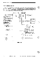
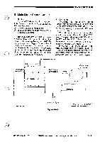
OPERATIONS AND TIMING= E. Main Motor Control Circuit 1. Outline Figure 3-107 shows the circuit that con- trols the main motor (M1); the circuit has the following functions: 01 turns on and off the main motor. 0 controls the rotation of the main motor to a specific revolution. The main motor (M1) is a DC motor with a built-in clock pulse generator. When the motor rotates, clock pulse signals (MMCLK) are generated according to the revolution of the motor. The speed control circuit matches the phases of the frequency of these clock pulses and the frequency of the reference signal to control the rotation of the main motor (M1) to a specific revolution. 2. Operation When the main motor drive signal (MMD) from the DC controller circuit goes '1', the drive circuit of the motor driver turns on, thereby rotating the main motor (M1) at a specific revolution. While the main motor is rotating at a specific revolution, the motor driver PCB sends the speed state signal (MLOCK=0) to the DC controller PCB. If, for some reason, fluctuations occur in the rotation of the main motor, the MLOCK signal goes '1'. If MLOCK=1 continues about 1 sec while the main motor drive signal (MMD) is '1', the DC controller identifies an error in the main motor, stops the main motor and, at the same time, indicates `E010' on the display. E IJ2O_15 i4 Composite j ;power supplyi J901 24V -1 l OV -2 1 MD -5 Phase control drive circuit Drive current Clock pulse generator Ml [..4 -6 MLOCK -6 1 Hall IC output MMCLK Reference signal Figure 3-107 Main motor control PCBJ COPYRIGHT © 1994 CANON INC. CANON PC7201740R501770 REV.0 AUG.1994 PRINTED IN JAPAN (IMPRIME AU JAPON) 3 - 7
-
 1
1 -
2
-
3
-
4
-
5
-
6
-
7
-
8
-
9
-
10
-
11
-
12
-
13
-
14
-
15
-
16
-
17
-
18
-
19
-
20
-
21
-
22
-
23
-
24
-
25
-
26
-
27
-
28
-
29
-
30
-
31
-
32
-
33
-
34
-
35
-
36
-
37
-
38
-
39
-
40
-
41
-
 42
42 -
 43
43 -
 44
44 -
 45
45 -
 46
46 -
 47
47 -
 48
48 -
 49
49 -
 50
50 -
 51
51 -
 52
52 -
53
-
54
-
55
-
56
-
57
-
58
-
59
-
60
-
61
-
62
-
63
-
64
-
65
-
66
-
67
-
68
-
69
-
70
-
71
-
72
-
73
-
74
-
75
-
76
-
77
-
78
-
79
-
80
-
81
-
82
-
83
-
84
-
85
-
86
-
87
-
88
-
89
-
90
-
91
-
92
-
93
-
94
-
95
-
96
-
97
-
98
-
99
-
100
-
101
-
102
-
103
-
104
-
105
-
106
-
107
-
108
-
109
-
110
-
111
-
112
-
113
-
114
-
115
-
116
-
117
-
118
-
119
-
120
-
121
-
122
-
123
-
124
-
125
-
126
-
127
-
128
-
129
-
130
-
131
-
132
-
133
-
134
-
135
-
136
-
137
-
138
-
139
-
140
-
141
-
142
-
143
-
144
-
145
-
146
-
147
-
148
-
149
-
150
-
151
-
152
-
153
-
154
-
155
-
156
-
157
-
158
-
159
-
160
-
161
-
162
-
163
-
164
-
165
-
166
-
167
-
168
-
169
-
170
-
171
-
172
-
173
-
174
-
175
-
176
-
177
-
178
-
179
-
180
-
181
-
182
-
183
-
184
-
185
-
186
-
187
-
188
-
189
-
190
-
191
-
192
-
193
-
194
-
195
-
196
-
197
-
198
-
199
-
200
 |
 |
