Canon PC740 Service Manual - Page 150
Composite, Power, Supply
 |
View all Canon PC740 manuals
Add to My Manuals
Save this manual to your list of manuals |
Page 150 highlights
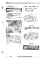
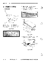
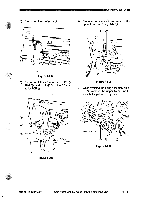
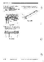
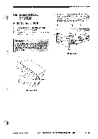
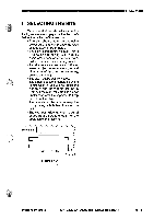
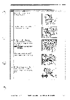
IIIIIIIMECHANICAL SYSTEM B. Composite Power Supply PCB 1. Removing the Composite Power Supply PCB 1) Open the copier's top unit. 2) Remove the left cover and the rear cover. 3) Remove the screw CD, and remove the copyboard cover support retainer O. e, 5) Remove the seven screws and remove the composite power supply PCB © while freeing the five claws ©. O • Figure 4-703 4) Disconnect the ten connectors CD from the composite power supply PCB ©. O O Figure 4-705 2. Points to Note When Handling the Composite Power Supply PCB Some capacitors on the composite power supply hold charges when the copier's power supply is off. Take extra care never to short the terminals of the capacitor whenever you have removed the composite power supply PCB. 4 0 4 0 0 4 Figure 4-704 4 - 34 COPYRIGHT 0 1994 CANON INC. CANON PC720R40R501770 REVD AUG.1994 PRINTEDIN JAPAN ompfut AU JAPON)
-
 1
1 -
2
-
3
-
4
-
5
-
6
-
7
-
8
-
9
-
10
-
11
-
12
-
13
-
14
-
15
-
16
-
17
-
18
-
19
-
20
-
21
-
22
-
23
-
24
-
25
-
26
-
27
-
28
-
29
-
30
-
31
-
32
-
33
-
34
-
35
-
36
-
37
-
38
-
39
-
40
-
41
-
42
-
43
-
44
-
45
-
46
-
47
-
48
-
49
-
50
-
51
-
52
-
53
-
54
-
55
-
56
-
57
-
58
-
59
-
60
-
61
-
62
-
63
-
64
-
65
-
66
-
67
-
68
-
69
-
70
-
71
-
72
-
73
-
74
-
75
-
76
-
77
-
78
-
79
-
80
-
81
-
82
-
83
-
84
-
85
-
86
-
87
-
88
-
89
-
90
-
91
-
92
-
93
-
94
-
95
-
96
-
97
-
98
-
99
-
100
-
101
-
102
-
103
-
104
-
105
-
106
-
107
-
108
-
109
-
110
-
111
-
112
-
113
-
114
-
115
-
116
-
117
-
118
-
119
-
120
-
121
-
122
-
123
-
124
-
125
-
126
-
127
-
128
-
129
-
130
-
131
-
132
-
133
-
134
-
135
-
136
-
137
-
138
-
139
-
140
-
141
-
142
-
143
-
144
-
 145
145 -
 146
146 -
 147
147 -
 148
148 -
 149
149 -
 150
150 -
 151
151 -
 152
152 -
 153
153 -
 154
154 -
 155
155 -
156
-
157
-
158
-
159
-
160
-
161
-
162
-
163
-
164
-
165
-
166
-
167
-
168
-
169
-
170
-
171
-
172
-
173
-
174
-
175
-
176
-
177
-
178
-
179
-
180
-
181
-
182
-
183
-
184
-
185
-
186
-
187
-
188
-
189
-
190
-
191
-
192
-
193
-
194
-
195
-
196
-
197
-
198
-
199
-
200
 |
 |
