Canon PC740 Service Manual - Page 143
disconnect
 |
View all Canon PC740 manuals
Add to My Manuals
Save this manual to your list of manuals |
Page 143 highlights
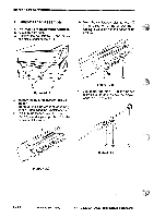
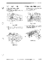
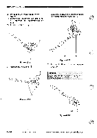
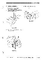
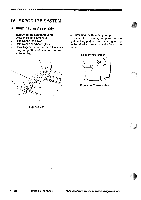
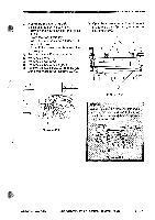
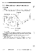
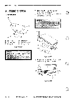
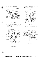
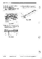
MECHANICAL SYSTEMMI 3. Removing the Blanking Unit 1) Select enlargement mode (141%). • Turn on the power switch, and select 141%. • Press the Copy Start key. • When the lens has moved farthest left, turn off the power. Turn off the power, and disconnect the power plug. 2) Remove the multifeeder assembly. 3) Remove the cartridge. 4) Remove the top cover. 5) Remove the DC controller PCB. 6) Remove the two screws C) from the rear of the composite power supply PCB (:). T U 0 0 7) Open the copier's top unit, and remove the four screws C); then, remove the blanking unit C). 0 Figure 4-404 0 0 0 O Figure 4-403 Caution: When installing the blanking unit, make sure that the blanking unit PCB is farthest to both ends and the copier's lens is at the farthest left. Lamp PCB Figure 4-405 COPYRIGHT 1994 CANON INC. CANON PC72017401750M0 REV.0 AUG.1994 PRINTED IN JAPAN iimPRimt AU JAPONI 4 - 27
-
 1
1 -
2
-
3
-
4
-
5
-
6
-
7
-
8
-
9
-
10
-
11
-
12
-
13
-
14
-
15
-
16
-
17
-
18
-
19
-
20
-
21
-
22
-
23
-
24
-
25
-
26
-
27
-
28
-
29
-
30
-
31
-
32
-
33
-
34
-
35
-
36
-
37
-
38
-
39
-
40
-
41
-
42
-
43
-
44
-
45
-
46
-
47
-
48
-
49
-
50
-
51
-
52
-
53
-
54
-
55
-
56
-
57
-
58
-
59
-
60
-
61
-
62
-
63
-
64
-
65
-
66
-
67
-
68
-
69
-
70
-
71
-
72
-
73
-
74
-
75
-
76
-
77
-
78
-
79
-
80
-
81
-
82
-
83
-
84
-
85
-
86
-
87
-
88
-
89
-
90
-
91
-
92
-
93
-
94
-
95
-
96
-
97
-
98
-
99
-
100
-
101
-
102
-
103
-
104
-
105
-
106
-
107
-
108
-
109
-
110
-
111
-
112
-
113
-
114
-
115
-
116
-
117
-
118
-
119
-
120
-
121
-
122
-
123
-
124
-
125
-
126
-
127
-
128
-
129
-
130
-
131
-
132
-
133
-
134
-
135
-
136
-
137
-
 138
138 -
 139
139 -
 140
140 -
 141
141 -
 142
142 -
 143
143 -
 144
144 -
 145
145 -
 146
146 -
 147
147 -
 148
148 -
149
-
150
-
151
-
152
-
153
-
154
-
155
-
156
-
157
-
158
-
159
-
160
-
161
-
162
-
163
-
164
-
165
-
166
-
167
-
168
-
169
-
170
-
171
-
172
-
173
-
174
-
175
-
176
-
177
-
178
-
179
-
180
-
181
-
182
-
183
-
184
-
185
-
186
-
187
-
188
-
189
-
190
-
191
-
192
-
193
-
194
-
195
-
196
-
197
-
198
-
199
-
200
 |
 |
