Canon PC740 Service Manual - Page 90
combination
 |
View all Canon PC740 manuals
Add to My Manuals
Save this manual to your list of manuals |
Page 90 highlights
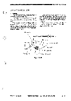
IINIOPERATIONS AND TIMING 3. Controlling the Power Supply to the Fixing Heater The temperature of the fixing heater is controlled by controlling the power supplied to the fixing heater. The power to the fixing heater is controlled by controlling its phase. The microprocessor on the DC controller PCB controls the output timing of the fixing heater driver signal (HTRD) so that power suited to the target temperature of the fixing heater may be supplied; this is to control the phase of the power supplied to the fixing heater. HTRD 4. Correcting the Variation in the Resistance of the Fixing Heater The plane-shaped heater used as the fixing heater has production variations in its resistance that would hinder proper execution of thermal control of the fixing heater. To correct possible problems, the copier compensates for the variations in terms of seven settings of the resistance, whose values are read by a microprocessor. CaUtion: The resistance of the fixing heater is decided based on the combination of the jumper wires connected to the connector of the thermistor (TH1); see Figure 3-414. The resistance is checked and appropriate settings are made at the factory when the fixing assembly is assembled; do not rearrange the jumper wires. Supply power to the heater Figure 3-413 0 0 Figure 3-414 3 - 50 COPYRIGHT © 1994 CANON INC. CANON PC120/74017501710 REVS AUG.1994 PRINTED IN JAPAN pipmmt AU JAPONI
-
 1
1 -
2
-
3
-
4
-
5
-
6
-
7
-
8
-
9
-
10
-
11
-
12
-
13
-
14
-
15
-
16
-
17
-
18
-
19
-
20
-
21
-
22
-
23
-
24
-
25
-
26
-
27
-
28
-
29
-
30
-
31
-
32
-
33
-
34
-
35
-
36
-
37
-
38
-
39
-
40
-
41
-
42
-
43
-
44
-
45
-
46
-
47
-
48
-
49
-
50
-
51
-
52
-
53
-
54
-
55
-
56
-
57
-
58
-
59
-
60
-
61
-
62
-
63
-
64
-
65
-
66
-
67
-
68
-
69
-
70
-
71
-
72
-
73
-
74
-
75
-
76
-
77
-
78
-
79
-
80
-
81
-
82
-
83
-
84
-
 85
85 -
 86
86 -
 87
87 -
 88
88 -
 89
89 -
 90
90 -
 91
91 -
 92
92 -
 93
93 -
 94
94 -
 95
95 -
96
-
97
-
98
-
99
-
100
-
101
-
102
-
103
-
104
-
105
-
106
-
107
-
108
-
109
-
110
-
111
-
112
-
113
-
114
-
115
-
116
-
117
-
118
-
119
-
120
-
121
-
122
-
123
-
124
-
125
-
126
-
127
-
128
-
129
-
130
-
131
-
132
-
133
-
134
-
135
-
136
-
137
-
138
-
139
-
140
-
141
-
142
-
143
-
144
-
145
-
146
-
147
-
148
-
149
-
150
-
151
-
152
-
153
-
154
-
155
-
156
-
157
-
158
-
159
-
160
-
161
-
162
-
163
-
164
-
165
-
166
-
167
-
168
-
169
-
170
-
171
-
172
-
173
-
174
-
175
-
176
-
177
-
178
-
179
-
180
-
181
-
182
-
183
-
184
-
185
-
186
-
187
-
188
-
189
-
190
-
191
-
192
-
193
-
194
-
195
-
196
-
197
-
198
-
199
-
200
 |
 |
