Canon PC740 Service Manual - Page 148
Mechanical, System
 |
View all Canon PC740 manuals
Add to My Manuals
Save this manual to your list of manuals |
Page 148 highlights
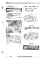
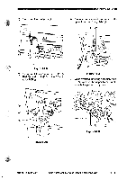
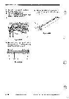
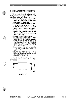
- MECHANICAL SYSTEM 2. Removing the Lower Fixing Roller 1) Open the copier's top unit. 2) Remove the delivery roller. (See "1. Removing the Delivery Roller' under "E. Delivery Assembly.") 3) 5) Remove the inlet guide retainer CI, and remove the inlet guide morf© the lower fixing roller. 3 3 CO Figure 4-608 4) Remove the two springs and two bushings 0, and remove the lower fixing roller CO and the inlet guide ©. Figure 4-610 Figure 4-609 4 - 32 COPYRIGHT © 1994 CANON INC. CANON PC720(7401750ITIO ROJO AUG. 1994 PRINTED IN JAPAN (IMPRIME AU JAPAN)
-
 1
1 -
2
-
3
-
4
-
5
-
6
-
7
-
8
-
9
-
10
-
11
-
12
-
13
-
14
-
15
-
16
-
17
-
18
-
19
-
20
-
21
-
22
-
23
-
24
-
25
-
26
-
27
-
28
-
29
-
30
-
31
-
32
-
33
-
34
-
35
-
36
-
37
-
38
-
39
-
40
-
41
-
42
-
43
-
44
-
45
-
46
-
47
-
48
-
49
-
50
-
51
-
52
-
53
-
54
-
55
-
56
-
57
-
58
-
59
-
60
-
61
-
62
-
63
-
64
-
65
-
66
-
67
-
68
-
69
-
70
-
71
-
72
-
73
-
74
-
75
-
76
-
77
-
78
-
79
-
80
-
81
-
82
-
83
-
84
-
85
-
86
-
87
-
88
-
89
-
90
-
91
-
92
-
93
-
94
-
95
-
96
-
97
-
98
-
99
-
100
-
101
-
102
-
103
-
104
-
105
-
106
-
107
-
108
-
109
-
110
-
111
-
112
-
113
-
114
-
115
-
116
-
117
-
118
-
119
-
120
-
121
-
122
-
123
-
124
-
125
-
126
-
127
-
128
-
129
-
130
-
131
-
132
-
133
-
134
-
135
-
136
-
137
-
138
-
139
-
140
-
141
-
142
-
 143
143 -
 144
144 -
 145
145 -
 146
146 -
 147
147 -
 148
148 -
 149
149 -
 150
150 -
 151
151 -
 152
152 -
 153
153 -
154
-
155
-
156
-
157
-
158
-
159
-
160
-
161
-
162
-
163
-
164
-
165
-
166
-
167
-
168
-
169
-
170
-
171
-
172
-
173
-
174
-
175
-
176
-
177
-
178
-
179
-
180
-
181
-
182
-
183
-
184
-
185
-
186
-
187
-
188
-
189
-
190
-
191
-
192
-
193
-
194
-
195
-
196
-
197
-
198
-
199
-
200
 |
 |

-
MECHANICAL
SYSTEM
2.
Removing
the
Lower
Fixing
Roller
5)
Remove
the
inlet
guide
retainer
CI,
and
1)
Open
the
copier's
top
unit.
remove
the
inlet
guide
the
lower
2)
Remove
the
delivery
roller.
fixing
roller.
(See
"1.
Removing
the
Delivery
Roller'
under
"E.
Delivery
Assembly.")
3)
3
Figure
4-610
3
CO
Figure
4-608
4)
Remove
the
two
springs
and
two
bushings
0,
and
remove
the
lower
fixing
roller
CO
and
the
inlet
guide
©.
Figure
4-609
4
-
32
COPYRIGHT
©
1994
CANON
INC.
CANON
PC720(7401750ITIO
ROJO
AUG.
1994
PRINTED
IN
JAPAN
(IMPRIME
AU
JAPAN)