Canon PC740 Service Manual - Page 42
Electrical, Circuitry
 |
View all Canon PC740 manuals
Add to My Manuals
Save this manual to your list of manuals |
Page 42 highlights
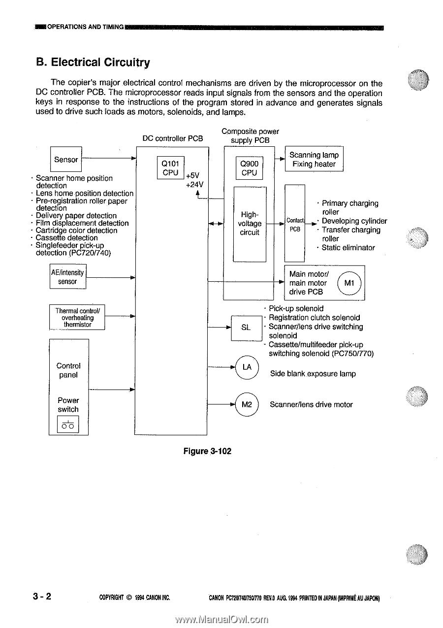
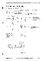
=OPERATIONS AND TIMING B. Electrical Circuitry The copier's major electrical control mechanisms are driven by the microprocessor on the DC controller PCB. The microprocessor reads input signals from the sensors and the operation keys in response to the instructions of the program stored in advance and generates signals used to drive such loads as motors, solenoids, and lamps. DC controller PCB Sensor • Scanner home position detection • Lens home position detection • Pre-registration roller paper detection • Delivery paper detection • Film displacement detection • Cartridge color detection • Cassette detection • Singlefeeder pick-up detection (PC720/740) Q101 CPU +5V +24V 4 Composite power supply PCB Q90O H Scanning lamp Fixing heater CPU Highvoltage circuit Contact PCB • Primary charging roller • Developing cylinder • Transfer charging roller • Static eliminator AE/intensity sensor Thermal control/ overheating thermistor Control panel SL • Main motor/ main motor drive PCB • Pick-up solenoid • Registration clutch solenoid • Scanner/lens drive switching solenoid • Cassette/multifeeder pick-up switching solenoid (PC750/770) Side blank exposure lamp Power switch 00 M2 Scanner/lens drive motor Figure 3-102 3- 2 COPYRIGHT © 1994 CANONINC. CANON PC72017050/770 REV.O AUG.1994 PRINTEDIN JAPANRout AU JAPON)
-
 1
1 -
2
-
3
-
4
-
5
-
6
-
7
-
8
-
9
-
10
-
11
-
12
-
13
-
14
-
15
-
16
-
17
-
18
-
19
-
20
-
21
-
22
-
23
-
24
-
25
-
26
-
27
-
28
-
29
-
30
-
31
-
32
-
33
-
34
-
35
-
36
-
 37
37 -
 38
38 -
 39
39 -
 40
40 -
 41
41 -
 42
42 -
 43
43 -
 44
44 -
 45
45 -
 46
46 -
 47
47 -
48
-
49
-
50
-
51
-
52
-
53
-
54
-
55
-
56
-
57
-
58
-
59
-
60
-
61
-
62
-
63
-
64
-
65
-
66
-
67
-
68
-
69
-
70
-
71
-
72
-
73
-
74
-
75
-
76
-
77
-
78
-
79
-
80
-
81
-
82
-
83
-
84
-
85
-
86
-
87
-
88
-
89
-
90
-
91
-
92
-
93
-
94
-
95
-
96
-
97
-
98
-
99
-
100
-
101
-
102
-
103
-
104
-
105
-
106
-
107
-
108
-
109
-
110
-
111
-
112
-
113
-
114
-
115
-
116
-
117
-
118
-
119
-
120
-
121
-
122
-
123
-
124
-
125
-
126
-
127
-
128
-
129
-
130
-
131
-
132
-
133
-
134
-
135
-
136
-
137
-
138
-
139
-
140
-
141
-
142
-
143
-
144
-
145
-
146
-
147
-
148
-
149
-
150
-
151
-
152
-
153
-
154
-
155
-
156
-
157
-
158
-
159
-
160
-
161
-
162
-
163
-
164
-
165
-
166
-
167
-
168
-
169
-
170
-
171
-
172
-
173
-
174
-
175
-
176
-
177
-
178
-
179
-
180
-
181
-
182
-
183
-
184
-
185
-
186
-
187
-
188
-
189
-
190
-
191
-
192
-
193
-
194
-
195
-
196
-
197
-
198
-
199
-
200
 |
 |