Canon PC740 Service Manual - Page 108
Vrios, Vrioi, Vr1oo, Vr102, Vr103
 |
View all Canon PC740 manuals
Add to My Manuals
Save this manual to your list of manuals |
Page 108 highlights
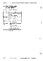
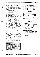
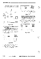
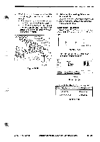
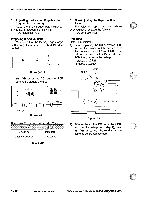
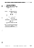
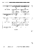
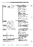
ENE OPERATIONS AND TIMING 5. Adjusting the Leading Edge Margin (registration on timing) Adjust the leading edge margin whenev- er you have replaced the following: • DC controller PCB Preparing for Adjustment Make sure that the leading edge margin is 0.2 to 5.0 mm when the Test Chart is copied. O.2 to 5.O [mm] Figure 3-710 1) Turn VR104 on the DC controller PCB so that the standard is met. 0 J0400033 1 VRIOI VR1OO :0- 40101 VRIOS VR102 VR103 PJ113 VR104 ,1105 3103 It. =J106 el Figure 3-711 Direction of VR104 and Leading Ed e Margin Direction Margin Clockwise Increases Counterclockwise Decreases Table 3-704 6. Fine-Adjusting the Reproduction Ratio Fine adjust the reproduction ratio whenever you have replaced the following: • DC controller PCB Preparing Obtain a multimeter. 1) Before replacing the DC controller PCB, turn on the power switch, and connect the probes to the CP23 and GND of the printed pattern on the DC controller PCB; then, measure the voltage. + probe CP23 - probe GND CP23 GND 0,D 0 IV°6. O O O 0 O 0000 Figure 3-712 2) After replacing the DC controller PCB, measure the voltage as in step 1); then, turn VR106 so that the reading is the same as before replacement. 3 - 68 COPYRIGHT © 1994 CANONINC. CANON PC72017401750fT/0REV.OAUG.1994 PRINTEDIN JAPAN ompRimtAUJAPON)
-
 1
1 -
2
-
3
-
4
-
5
-
6
-
7
-
8
-
9
-
10
-
11
-
12
-
13
-
14
-
15
-
16
-
17
-
18
-
19
-
20
-
21
-
22
-
23
-
24
-
25
-
26
-
27
-
28
-
29
-
30
-
31
-
32
-
33
-
34
-
35
-
36
-
37
-
38
-
39
-
40
-
41
-
42
-
43
-
44
-
45
-
46
-
47
-
48
-
49
-
50
-
51
-
52
-
53
-
54
-
55
-
56
-
57
-
58
-
59
-
60
-
61
-
62
-
63
-
64
-
65
-
66
-
67
-
68
-
69
-
70
-
71
-
72
-
73
-
74
-
75
-
76
-
77
-
78
-
79
-
80
-
81
-
82
-
83
-
84
-
85
-
86
-
87
-
88
-
89
-
90
-
91
-
92
-
93
-
94
-
95
-
96
-
97
-
98
-
99
-
100
-
101
-
102
-
 103
103 -
 104
104 -
 105
105 -
 106
106 -
 107
107 -
 108
108 -
 109
109 -
 110
110 -
 111
111 -
 112
112 -
 113
113 -
114
-
115
-
116
-
117
-
118
-
119
-
120
-
121
-
122
-
123
-
124
-
125
-
126
-
127
-
128
-
129
-
130
-
131
-
132
-
133
-
134
-
135
-
136
-
137
-
138
-
139
-
140
-
141
-
142
-
143
-
144
-
145
-
146
-
147
-
148
-
149
-
150
-
151
-
152
-
153
-
154
-
155
-
156
-
157
-
158
-
159
-
160
-
161
-
162
-
163
-
164
-
165
-
166
-
167
-
168
-
169
-
170
-
171
-
172
-
173
-
174
-
175
-
176
-
177
-
178
-
179
-
180
-
181
-
182
-
183
-
184
-
185
-
186
-
187
-
188
-
189
-
190
-
191
-
192
-
193
-
194
-
195
-
196
-
197
-
198
-
199
-
200
 |
 |
