Cisco SPA1001 Administration Guide - Page 43
Making the Physical Connections
 |
View all Cisco SPA1001 manuals
Add to My Manuals
Save this manual to your list of manuals |
Page 43 highlights
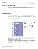
Chapter 2 Getting Started http://www.erlang.com/calculator/lipb/ http://www.packetizer.com/voip/diagnostics/bandcalc.html Establishing Connectivity Making the Physical Connections Make sure that you have the following package contents: • Linksys phone adapter unit • Ethernet cable • RJ-11 phone cable (SPA3102/AG310 Only) • SPA Quickstart Guide • Volt power adapter You also need the following: • One or two analog touchtone telephones (or fax Machine) • Access to an IP network via an Ethernet connection for WAN connectivity • Access to a PSTN network connection (SPA3102/AG310 only). Perform the following steps to connect the Linksys ATA. Step 1 Step 2 Step 3 Step 4 Insert a standard RJ-45 Ethernet cable (included) into the LAN port and connect the other end to the broadband router or modem. (Optional) For a Linksys ATA with more than one Ethernet port, you can connect the extra port to a PC or other Ethernet device. Insert a standard RJ-11 telephone cable into the Phone 1 port. (Optional) For a Linksys ATA with more than one FXS port, you can connect the extra port to a second analog telephone or a fax machine. Note Do not connect an RJ-11 telephone cable from the Linksys ATA to the wall jack to prevent any chance of connection to the circuit switched Telco network. Step 5 Step 6 Step 7 (SPA3102/AG310 only) Connect the RJ-11 phone cable (included) to the SPA3102 LINE port and to your telephofne wall jack. Connect the included power adapter to the Linksys ATA power port, and then plug the power adapter into an electrical outlet. The power LED on the front panel will light up as soon as the device powers on. Power on the broadband modem or router. Document Version 3.1 Linksys ATA Administrator Guide 2-15
-
 1
1 -
2
-
3
-
4
-
5
-
6
-
7
-
8
-
9
-
10
-
11
-
12
-
13
-
14
-
15
-
16
-
17
-
18
-
19
-
20
-
21
-
22
-
23
-
24
-
25
-
26
-
27
-
28
-
29
-
30
-
31
-
32
-
33
-
34
-
35
-
36
-
37
-
 38
38 -
 39
39 -
 40
40 -
 41
41 -
 42
42 -
 43
43 -
 44
44 -
 45
45 -
 46
46 -
 47
47 -
 48
48 -
49
-
50
-
51
-
52
-
53
-
54
-
55
-
56
-
57
-
58
-
59
-
60
-
61
-
62
-
63
-
64
-
65
-
66
-
67
-
68
-
69
-
70
-
71
-
72
-
73
-
74
-
75
-
76
-
77
-
78
-
79
-
80
-
81
-
82
-
83
-
84
-
85
-
86
-
87
-
88
-
89
-
90
-
91
-
92
-
93
-
94
-
95
-
96
-
97
-
98
-
99
-
100
-
101
-
102
-
103
-
104
-
105
-
106
-
107
-
108
-
109
-
110
-
111
-
112
-
113
-
114
-
115
-
116
-
117
-
118
-
119
-
120
-
121
-
122
-
123
-
124
-
125
-
126
-
127
-
128
-
129
-
130
-
131
-
132
-
133
-
134
-
135
-
136
-
137
-
138
-
139
-
140
-
141
-
142
-
143
-
144
-
145
-
146
-
147
-
148
-
149
-
150
-
151
-
152
-
153
-
154
-
155
-
156
-
157
-
158
-
159
-
160
-
161
-
162
-
163
-
164
-
165
-
166
-
167
-
168
-
169
-
170
-
171
-
172
-
173
-
174
-
175
-
176
-
177
-
178
-
179
-
180
-
181
-
182
-
183
-
184
-
185
-
186
 |
 |
