Cub Cadet XT2 SLX54 Operation Manual - Page 21
Service, Electrical System, Relays and Switches, Parking Brake Adjustment, Hydrostatic Neutral
 |
View all Cub Cadet XT2 SLX54 manuals
Add to My Manuals
Save this manual to your list of manuals |
Page 21 highlights
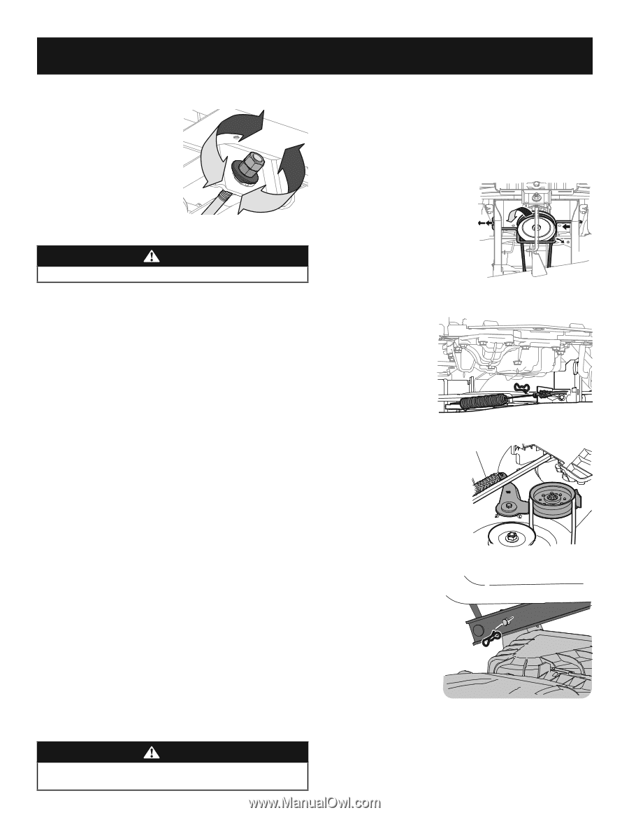
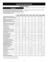
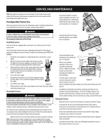
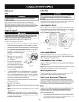
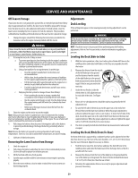
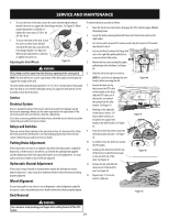
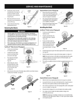
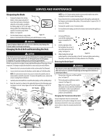
SERVICE AND MAINTENANCE 4. To raise the front of the deck, loosen the outer nut then tighten (thread inward) the inner nut against the front hanger bracket. See Figure 39. When proper adjustment is achieved, retighten the outer nut to 25-30 ft.-lbs (34-40.7 N-m). 5. To lower the front of the deck, loosen the outer nut then loosen (thread outward) the inner nut, away from the front hanger bracket. See Figure 39. When proper adjustment is achieved, re-tighten the outer nut. Adjusting the Deck Wheels Figure 39 WARNING Keep hands and feet away from the discharge opening of the cutting deck. NOTE: The deck wheels are an anti-scalp feature of the deck and are not designed to support the weight of the deck. The deck wheels should be approximately 1⁄4-1⁄2" (6.35-12.7mm) above the ground when the deck is set in the desired height setting. To adjust the deck wheels see the Assembly section for instructions. Service Electrical System A fuse is installed to protect the tractor's electrical system from damage caused by excessive amperage. Always use the same capacity fuse for replacement. If the electrical system does not function, check for a blown fuse. If you have a recurring problem with blown fuses, have the tractor's electrical system checked by your authorized service dealer. Relays and Switches There are several safety switches in the electrical system. If a function of the safety interlock system described earlier is not functioning properly, have the electrical system checked by your authorized service dealer. Parking Brake Adjustment If the tractor does not come to a complete stop when the brake pedal is completely depressed, or if the tractor's rear wheels can roll with the parking brake applied (and the hydrostatic relief valve open), the brake is in need of adjustment. See your authorized service dealer to have the brake adjusted. Hydrostatic Neutral Adjustment If the tractor creeps forward or rearward when neither the forward nor reverse pedal is depressed, contact your local authorized dealer to have the neutral setting properly adjusted. Wheel Alignment If your tractor pulls to one side or is out of alignment, a wheel alignment might be necessary. Contact an authorized service dealer to have the wheels properly aligned. Deck Removal To remove the deck, proceed as follows: 1. Move the tractor to a level surface, disengage the PTO, stop the engine, ENGAGE the parking brake. 2. Lower the deck by moving the deck lift lever into the bottom notch on the right fender. 3. For tractors with a manual PTO continue with step 4, for electric PTO models skip ahead to step 8. 4. Loosen, but do not remove the flange lock nut on the right idler pulley and the hex screw on the left idler pulley. 5. Remove the hex screw securing the engine pulley keeper rod to the frame. See Figure 40. 6. Slide the rod to the right to remove it. NOTE: Be careful not to damage the wire harness when removing the rod. 7. Remove the bow tie clip that secures the PTO cable to the bracket on the deck, slide the PTO cable out of the bracket and unhook the spring from the idler bracket. See Figure 41. Figure 40 8. Working on the right side of the tractor, insert a 3⁄8" drive ratchet wrench, set to tighten, into square hole found on the idler bracket. See Figure 42. Figure 41 9. Pivot the wrench forward to move the deck drive pulley forward. See Figure 42. 10. Carefully remove the belt from around the PTO pulley. 11. Looking at the deck from the left side of the tractor, locate the bow-tie pin on the rear left side of the deck. See Figure 43. 12. Remove the pin and slide the deck pin out of the deck lift arm. See Figure 43. 13. Repeat steps 11-12 on the tractor's right side. Figure 42 Figure 43 WARNING Use caution to avoid pinching your fingers when rolling the belt off the PTO pulley. 21
-
 1
1 -
2
-
3
-
4
-
5
-
6
-
7
-
8
-
9
-
10
-
11
-
12
-
13
-
14
-
15
-
 16
16 -
 17
17 -
 18
18 -
 19
19 -
 20
20 -
 21
21 -
 22
22 -
 23
23 -
 24
24 -
 25
25 -
 26
26 -
27
-
28
-
29
-
30
-
31
-
32
-
33
-
34
-
35
-
36
-
37
-
38
-
39
-
40
-
41
-
42
-
43
-
44
-
45
-
46
-
47
-
48
-
49
-
50
-
51
-
52
-
53
-
54
-
55
-
56
-
57
-
58
-
59
-
60
-
61
-
62
-
63
-
64
-
65
-
66
-
67
-
68
-
69
-
70
-
71
-
72
 |
 |