Cub Cadet XT2 SLX54 Operation Manual - Page 7
Assembly
 |
View all Cub Cadet XT2 SLX54 manuals
Add to My Manuals
Save this manual to your list of manuals |
Page 7 highlights
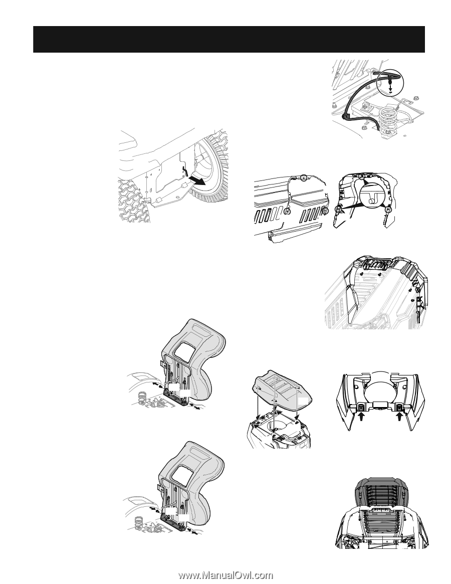
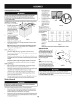
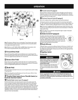
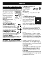
ASSEMBLY Note: This Operator's Manual covers several models. Tractor features may vary by model. Not all features in this manual are applicable to all tractor models and the tractor depicted may differ from yours. Note: All references in this manual to the left or right side and front or back of the tractor are from the operating position only. Exceptions, if any, will be specified. Preparation Manually Moving the Tractor 1. Engage the transmission bypass rod to move the tractor manually without starting it. The transmission bypass rod is located on the rear of the tractor, on the frame. Engage the bypass rod by pulling out. See Figure 1. NOTE: If the tractor will not move or does not move freely when pushing check if the hydrostatic bypass rod is fully open or the brake is engaged. NOTE: The transmission will Figure 1 NOT engage when the hydrostatic bypass rod is pulled out. Return the rod to its disengaged position prior to operating the tractor. 2. Disengage the transmission bypass rod by pushing the rod back in after moving the tractor. See Figure 1. Install Operator's Seat (If necessary) To install the seat proceed as follows: NOTE: The seat is shipped with the seat switch and seat pan attached. 1. Cut any straps securing the seat assembly to the tractor. Remove any packing material. NOTE: Be careful not to cut the wiring harness connecting the seat and the seat switch. 2. Remove the two shoulder bolts (a) and flange lock nuts (b) in the seat pan as shown in Figure 2. 3. Rotate the seat into position and slide a Phillips screwdriver through one of the seatsecuring holes and seat bracket for alignment. 4. With the previously removed shoulder bolts (a) and flange lock nuts (b) secure one side of the seat and seat bracket. While supporting the seat, remove the Phillips screwdriver and secure the other side of the seat. Be careful not to crimp or damage the wire harness while installing the seat. See Figure 3. Torque to 84-103 in-lbs (9.511.6 N-m). (a) (b) (b) (a) Figure 2 (a) (b) (b) (a) Figure 3 5. Using the harness clip attached to the harness, secure the excess wire to the fender by snapping the harness clip in place as shown in Figure 4. Installing the Hood Collar (If necessary) There are three (3) alignment posts (a) on the hood collar (b) that line up with corresponding alignment holes (c) in the hood (d). See Figure 5 (c) (b) (d) Figure 4 (a) (c) (c) (a) (a) (a) Figure 5 a Use these alignment points to properly position the hood collar (a), then secure it in place with the six hex bolts (b) provided in the hardware bag. See Figure 8. Tighten the hex bolts to 102-124 in-lbs (11.5-14 N-m). See Figure 6. Installing the Snap-On Hood bb b b Topper (If necessary) 1. To install the snap-on hood topper (a), line up the holes on the hood topper (a) up with the Figure 6 tabs (b) in the hood frame as shown in Figure 7. 2. Insert the tabs (b) into the hood topper and pull back to lock into place. (a) (b) (b) (b) (b) Figure 7 Hood Topper Not Shown for Clarity Figure 8 3. Once the hood topper is in place, the two locking tabs near the rear of the hood need to be pushed upward to lock the hood topper in place. See Figure 8. Installing the Screw-On Hood (a) Topper (If necessary) Note: Be careful not to damage the headlight harness when installing the screw-on hood topper. 1. Set the hood topper up against the top of the hood with the hood open, and align the holes on the hood. (c) (b) (d) (b) (d) Figure 9 7
-
 1
1 -
 2
2 -
 3
3 -
 4
4 -
 5
5 -
 6
6 -
 7
7 -
 8
8 -
 9
9 -
 10
10 -
 11
11 -
 12
12 -
13
-
14
-
15
-
16
-
17
-
18
-
19
-
20
-
21
-
22
-
23
-
24
-
25
-
26
-
27
-
28
-
29
-
30
-
31
-
32
-
33
-
34
-
35
-
36
-
37
-
38
-
39
-
40
-
41
-
42
-
43
-
44
-
45
-
46
-
47
-
48
-
49
-
50
-
51
-
52
-
53
-
54
-
55
-
56
-
57
-
58
-
59
-
60
-
61
-
62
-
63
-
64
-
65
-
66
-
67
-
68
-
69
-
70
-
71
-
72
 |
 |