D-Link DES-3228PA Installation Guide - Page 97
Defining STP on Interfaces, Configuring Spanning Tree, STP Interface
 |
UPC - 790069296352
View all D-Link DES-3228PA manuals
Add to My Manuals
Save this manual to your list of manuals |
Page 97 highlights
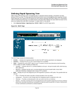
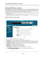
Configuring Spanning Tree Defining STP on Interfaces Defining STP on Interfaces Network administrators can assign STP settings to specific interfaces using the STP Interface Page. The Global LAGs section displays the STP information for Link Aggregated Groups. To assign STP settings to an interface: 1. Click Advanced Setup > Spanning Tree > STP > Interface Settings. The STP Interface Page opens: Figure 48: STP Interface Page The STP Interface Page contains the following fields: • Unit No. -Indicates the stacking member for which the STP interface parameters are displayed. • Port - The port for which the information is displayed. • STP - Indicates if STP is enabled on the port. The possible field values are: - Enabled - Indicates that STP is enabled on the port. - Disabled - Indicates that STP is disabled on the port. • Fast Link - Indicates if Fast Link is enabled on the port. If Fast Link mode is enabled for a port, the Port State is automatically placed in the Forwarding state when the port link is up. Fast Link optimizes the STP protocol convergence. STP convergence can take 30-60 seconds in large networks. • Root Guard - Restricts the interface from acting as the root port of the switch. • Port State - Displays the current STP state of a port. If enabled, the port state determines what forwarding action is taken on traffic. Possible port states are: - Disabled - Indicates that STP is currently disabled on the port. The port forwards traffic while learning MAC addresses. - Blocking - Indicates that the port is currently blocked and cannot forward traffic or learn MAC addresses. Blocking is displayed when Classic STP is enabled. • Port Role - Displays the port role assigned by the STP algorithm to provide to STP paths. The possible field values are: - Root - Provides the lowest cost path to forward packets to the root switch. - Designated - The port or LAG through which the designated switch is attached to the LAN. Page 94
-
 1
1 -
2
-
3
-
4
-
5
-
6
-
7
-
8
-
9
-
10
-
11
-
12
-
13
-
14
-
15
-
16
-
17
-
18
-
19
-
20
-
21
-
22
-
23
-
24
-
25
-
26
-
27
-
28
-
29
-
30
-
31
-
32
-
33
-
34
-
35
-
36
-
37
-
38
-
39
-
40
-
41
-
42
-
43
-
44
-
45
-
46
-
47
-
48
-
49
-
50
-
51
-
52
-
53
-
54
-
55
-
56
-
57
-
58
-
59
-
60
-
61
-
62
-
63
-
64
-
65
-
66
-
67
-
68
-
69
-
70
-
71
-
72
-
73
-
74
-
75
-
76
-
77
-
78
-
79
-
80
-
81
-
82
-
83
-
84
-
85
-
86
-
87
-
88
-
89
-
90
-
91
-
 92
92 -
 93
93 -
 94
94 -
 95
95 -
 96
96 -
 97
97 -
 98
98 -
 99
99 -
 100
100 -
 101
101 -
 102
102 -
103
-
104
-
105
-
106
-
107
-
108
-
109
-
110
-
111
-
112
-
113
-
114
-
115
-
116
-
117
-
118
-
119
-
120
-
121
-
122
-
123
-
124
-
125
-
126
-
127
-
128
-
129
-
130
-
131
-
132
-
133
-
134
-
135
-
136
-
137
-
138
-
139
-
140
-
141
-
142
-
143
-
144
-
145
-
146
-
147
-
148
-
149
-
150
-
151
-
152
-
153
-
154
-
155
-
156
-
157
-
158
-
159
-
160
-
161
-
162
-
163
-
164
-
165
-
166
-
167
-
168
-
169
-
170
-
171
-
172
-
173
-
174
-
175
-
176
-
177
-
178
-
179
-
180
-
181
-
182
-
183
-
184
-
185
-
186
-
187
-
188
-
189
-
190
-
191
-
192
-
193
-
194
-
195
-
196
-
197
-
198
-
199
-
200
-
201
-
202
-
203
-
204
-
205
-
206
-
207
-
208
-
209
-
210
-
211
-
212
-
213
-
214
-
215
-
216
-
217
-
218
-
219
-
220
-
221
-
222
-
223
-
224
-
225
-
226
-
227
-
228
-
229
-
230
-
231
-
232
-
233
-
234
-
235
-
236
-
237
-
238
-
239
-
240
-
241
-
242
-
243
-
244
-
245
-
246
-
247
-
248
-
249
-
250
-
251
-
252
-
253
-
254
-
255
-
256
-
257
-
258
-
259
-
260
-
261
-
262
-
263
-
264
-
265
-
266
-
267
-
268
-
269
-
270
-
271
-
272
-
273
-
274
 |
 |
