D-Link DXS-1100-10TS User Manual - Page 73
L2 Features > L2 Multicast Control> IGMP Snooping > IGMP Snooping Settings, Destination MAC
 |
View all D-Link DXS-1100-10TS manuals
Add to My Manuals
Save this manual to your list of manuals |
Page 73 highlights
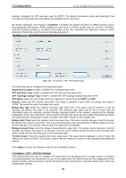
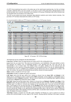
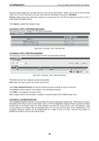
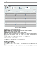
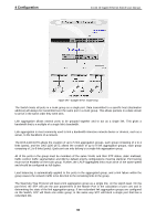
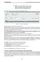
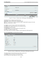
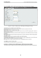
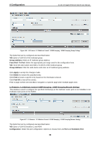
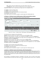
4 Configuration D-Link 10 Gigabit Ethernet Switch User Manual NOTE: If any ports within the trunk group become disconnected, packets intended for the disconnected port will be load shared among the other linked ports of the link aggregation group. This window is used to view and configure the link aggregation settings. Figure 4.92 - L2 Features > Link Aggregation The fields that can be configured are described below: System Priority: Enter the system's priority value used here. This value must be between 1 and 65535. By default, this value is 32768. The system priority determines which ports can join a port-channel and which ports are put in the stand-alone mode. The lower value has a higher priority. If two or more ports have the same priority, the port number determines the priority. Load Balance Algorithm: Select the load balancing algorithm that will be used here. Options to choose from are Source MAC, Destination MAC, Source Destination MAC, Source IP, Destination IP, and Source Destination IP. By default, this option is Source MAC. From Port / To Port: Select the appropriate port range used for the configuration here. Group ID: Enter the channel group number here. This value must be between 1 and 8. The system will automatically create the port-channel when a physical port first joins a channel group. An interface can only join one channel-group. Mode: Select the mode option here. Options to choose from are On, Active, and Passive. If the mode On is specified, the channel group type is static. If the mode Active or Passive is specified, the channel group type is LACP. A channel group can only consist of either static members or LACP members. Once the type of channel group has been determined, other types of interfaces cannot join the channel group. Click Apply to accept the changes made for each individual section. Click Add to add a new entry based on the information entered. Click Delete Member Port to remove the specific member port. Click Delete Channel to remove the specific entry. Click Channel Detail to view more detailed information about the channel. After clicking Channel Detail, the following page will be available. L2 Features > L2 Multicast Control> IGMP Snooping > IGMP Snooping Settings In order to use IGMP Snooping it must first be enabled for the entire Switch under IGMP Global Settings at the top of the window. You may then fine-tune the settings for each VLAN by clicking the corresponding Edit button. When enabled for IGMP snooping, the Switch can open or close a port to a specific multicast group member based on IGMP messages sent from the device to the IGMP host or vice versa. The Switch monitors IGMP messages and discontinues forwarding multicast packets when there are no longer hosts requesting that they continue. 66
-
 1
1 -
2
-
3
-
4
-
5
-
6
-
7
-
8
-
9
-
10
-
11
-
12
-
13
-
14
-
15
-
16
-
17
-
18
-
19
-
20
-
21
-
22
-
23
-
24
-
25
-
26
-
27
-
28
-
29
-
30
-
31
-
32
-
33
-
34
-
35
-
36
-
37
-
38
-
39
-
40
-
41
-
42
-
43
-
44
-
45
-
46
-
47
-
48
-
49
-
50
-
51
-
52
-
53
-
54
-
55
-
56
-
57
-
58
-
59
-
60
-
61
-
62
-
63
-
64
-
65
-
66
-
67
-
 68
68 -
 69
69 -
 70
70 -
 71
71 -
 72
72 -
 73
73 -
 74
74 -
 75
75 -
 76
76 -
 77
77 -
 78
78 -
79
-
80
-
81
-
82
-
83
-
84
-
85
-
86
-
87
-
88
-
89
-
90
-
91
-
92
-
93
-
94
-
95
-
96
-
97
-
98
-
99
-
100
-
101
-
102
-
103
-
104
-
105
-
106
-
107
-
108
-
109
-
110
-
111
-
112
-
113
-
114
-
115
-
116
-
117
-
118
-
119
-
120
-
121
 |
 |
