| Section |
Page |
| Contents |
2 |
| Safety information |
8 |
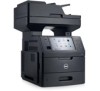
| Learning about the printer |
10 |
| Finding information about the printer |
10 |
| Selecting a location for the printer |
11 |
| Printer configurations |
12 |
| Understanding the basic functions of the scanner |
14 |
| Using the ADF and scanner glass |
15 |
| Understanding the printer control panel |
16 |
| Using the printer control panel |
16 |
| Understanding the colors of the indicator and Sleep button lights |
16 |
| Understanding the home screen |
17 |
| Using the touch-screen buttons |
19 |
| Setting up and using the home screen applications |
21 |
| Finding the IP address of the printer |
21 |
| Finding the IP address of the computer |
21 |
| Accessing the Embedded Web Server |
22 |
| Customizing the home screen |
22 |
| Understanding the different applications |
22 |
| Activating the home screen applications |
23 |
| Finding information about the home screen applications |
23 |
| Setting up Forms and Favorites |
23 |
| Setting up Card Copy |
24 |
| Using MyShortcut |
25 |
| Setting up Multi Send |
25 |
| Setting up Scan to Network |
26 |
| Setting up Remote Operator Panel |
26 |
| Exporting and importing a configuration |
27 |
| Additional printer setup |
28 |
| Installing internal options |
28 |
| Available internal options |
28 |
| Accessing the controller board |
29 |
| Installing a memory card |
32 |
| Installing an optional card |
34 |
| Installing an Internal Solutions Port |
36 |
| Installing a printer hard disk |
41 |
| Removing a printer hard disk |
45 |
| Installing hardware options |
47 |
| Order of installation |
47 |
| Installing optional trays |
47 |
| Attaching cables |
50 |
| Setting up the printer software |
52 |
| Installing the printer software |
52 |
| Updating available options in the printer driver |
52 |
| Networking |
53 |
| Preparing to set up the printer on an Ethernet network |
53 |
| Installing the printer on an Ethernet network |
53 |
| Preparing to set up the printer on a wireless network |
55 |
| Connecting the printer using the Wireless Setup Wizard |
56 |
| Connecting the printer to a wireless network using Wi-Fi Protected Setup |
56 |
| Connecting the printer to a wireless network using the Embedded Web Server |
57 |
| Changing port settings after installing a new network Internal Solutions Port |
58 |
| Setting up serial printing |
59 |
| Verifying printer setup |
60 |
| Printing a menu settings page |
60 |
| Printing a network setup page |
60 |
| Loading paper and specialty media |
61 |
| Setting the paper size and type |
61 |
| Configuring Universal paper settings |
61 |
| Loading the 550-sheet tray |
61 |
| Loading the 2100-sheet tray |
67 |
| Loading the multipurpose feeder |
73 |
| Linking and unlinking trays |
77 |
| Linking and unlinking trays |
77 |
| Creating a custom name for a paper type |
78 |
| Assigning a custom paper type |
78 |
| Paper and specialty media guide |
80 |
| Paper guidelines |
80 |
| Paper characteristics |
80 |
| Selecting paper |
81 |
| Selecting preprinted forms and letterhead |
81 |
| Using recycled paper and other office papers |
81 |
| Storing paper |
83 |
| Supported paper sizes, types, and weights |
83 |
| Supported paper sizes |
83 |
| Supported paper types and weights |
84 |
| Printing |
86 |
| Printing forms and a document |
86 |
| Printing forms |
86 |
| Printing a document |
86 |
| Adjusting toner darkness |
86 |
| Printing from a flash drive |
87 |
| Printing from a flash drive |
87 |
| Supported flash drives and file types |
88 |
| Using specialty media |
89 |
| Tips on using card stock |
89 |
| Tips on using envelopes |
89 |
| Tips on using labels |
90 |
| Tips on using letterhead |
90 |
| Tips on using transparencies |
91 |
| Printing confidential and other held jobs |
91 |
| Storing print jobs in the printer |
91 |
| Printing confidential and other held jobs |
92 |
| Modifying confidential print settings |
93 |
| Printing information pages |
93 |
| Printing a font sample list |
93 |
| Printing a directory list |
93 |
| Canceling a print job |
93 |
| Canceling a print job from the printer control panel |
93 |
| Canceling a print job from the computer |
94 |
| Copying |
95 |
| Making copies |
95 |
| Making a quick copy |
95 |
| Copying using the ADF |
95 |
| Copying using the scanner glass |
96 |
| Copying photos |
96 |
| Copying on specialty media |
96 |
| Copying on transparencies |
96 |
| Copying on letterhead |
97 |
| Customizing copy settings |
97 |
| Copying to a different size |
97 |
| Making copies using paper from a selected tray |
98 |
| Copying different paper sizes |
98 |
| Copying on both sides of the paper (duplexing) |
99 |
| Reducing or enlarging copies |
99 |
| Adjusting copy quality |
100 |
| Collating copies |
100 |
| Placing separator sheets between copies |
101 |
| Copying multiple pages onto a single sheet |
101 |
| Creating a custom copy job |
102 |
| Placing information on copies |
103 |
| Placing a header or footer on pages |
103 |
| Placing an overlay message on each page |
103 |
| Canceling a copy job |
103 |
| Canceling a copy job while the original document is in the ADF |
103 |
| Canceling a copy job while copying pages using the scanner glass |
103 |
| Canceling a copy job while pages are being printed |
104 |
| Understanding the copy options |
104 |
| Copy from |
104 |
| Copy to |
104 |
| Scale |
104 |
| Darkness |
104 |
| Sides (Duplex) |
104 |
| Collate |
105 |
| Copies |
105 |
| Content |
105 |
| Save As Shortcut |
105 |
| Using the advanced options |
105 |
| E-mailing |
107 |
| Setting up the printer to e-mail |
107 |
| Setting up the e-mail function |
107 |
| Configuring e-mail settings |
107 |
| Creating an e-mail shortcut |
108 |
| Creating an e-mail shortcut using the Embedded Web Server |
108 |
| Creating an e-mail shortcut using the printer control panel |
108 |
| E-mailing a document |
109 |
| Sending an e-mail using the printer control panel |
109 |
| Sending an e-mail using a shortcut number |
109 |
| Sending an e-mail using the address book |
110 |
| Customizing e-mail settings |
110 |
| Adding e-mail subject and message information |
110 |
| Changing the output file type |
110 |
| Canceling an e-mail |
111 |
| Understanding the e-mail options |
111 |
| Recipient(s) |
111 |
| Subject |
111 |
| Message |
111 |
| File Name |
111 |
| Save As Shortcut |
111 |
| Original Size |
112 |
| Darkness |
112 |
| Resolution |
112 |
| Content |
112 |
| Send As |
112 |
| Page Setup |
113 |
| Scan Preview |
113 |
| Using the advanced options |
113 |
| Faxing |
114 |
| Setting up the printer to fax |
114 |
| Initial fax setup |
115 |
| Choosing a fax connection |
116 |
| Scenario 1: Standard telephone line |
116 |
| Scenario 2: Digital Subscriber Line (DSL) |
120 |
| Scenario 3: VoIP telephone service |
121 |
| Scenario 4: Digital telephone service through a cable provider |
122 |
| Scenario 5: Countries or regions with different telephone wall jacks and plugs |
124 |
| Connecting to a distinctive ring service |
128 |
| Setting the outgoing fax name and number |
128 |
| Setting the date and time |
129 |
| Configuring the printer to observe daylight saving time |
129 |
| Sending a fax |
129 |
| Sending a fax using the printer control panel |
129 |
| Sending a fax using the computer |
130 |
| Sending a fax using a shortcut number |
130 |
| Sending a fax using the address book |
131 |
| Sending a fax at a scheduled time |
131 |
| Creating shortcuts |
132 |
| Creating a fax destination shortcut using the Embedded Web Server |
132 |
| Creating a fax destination shortcut using the printer control panel |
132 |
| Customizing fax settings |
132 |
| Changing the fax resolution |
132 |
| Making a fax lighter or darker |
133 |
| Viewing a fax log |
133 |
| Blocking junk faxes |
133 |
| Canceling an outgoing fax |
134 |
| Canceling a fax while the original documents are still scanning |
134 |
| Canceling a fax after the original documents have been scanned to memory |
134 |
| Holding and forwarding faxes |
134 |
| Holding faxes |
134 |
| Forwarding a fax |
135 |
| Understanding the fax options |
135 |
| Content |
135 |
| Resolution |
136 |
| Darkness |
136 |
| Page Setup |
136 |
| Scan Preview |
136 |
| Delayed Send |
136 |
| Using the advanced options |
137 |
| Scanning |
138 |
| Using Scan to Network |
138 |
| Scanning to an FTP address |
138 |
| Creating shortcuts |
138 |
| Creating an FTP shortcut using the Embedded Web Server |
138 |
| Creating an FTP shortcut using the printer control panel |
139 |
| Scanning to an FTP address |
139 |
| Scanning to an FTP address using the printer control panel |
139 |
| Scanning to an FTP address using a shortcut number |
139 |
| Scanning an FTP using the address book |
140 |
| Scanning to a computer or flash drive |
140 |
| Scanning to a computer using the Embedded Web Server |
141 |
| Setting up Scan to Computer |
141 |
| Scanning to a flash drive |
142 |
| Understanding the scan options |
143 |
| FTP |
143 |
| File Name |
143 |
| Save As Shortcut |
143 |
| Original Size |
143 |
| Send As |
143 |
| Resolution |
143 |
| Darkness |
143 |
| Page Setup |
144 |
| Content |
144 |
| Scan Preview |
144 |
| Using the advanced options |
144 |
| Understanding the printer menus |
146 |
| Menus list |
146 |
| Paper menu |
147 |
| Default Source menu |
147 |
| Configure MP menu |
147 |
| Paper Size/Type menu |
148 |
| Substitute Size menu |
151 |
| Paper Texture menu |
151 |
| Paper Weight menu |
153 |
| Paper Loading menu |
155 |
| Custom Types menu |
156 |
| Custom Names menu |
156 |
| Custom Scan Sizes menu |
157 |
| Universal Setup menu |
157 |
| Reports Menu |
158 |
| Reports menu |
158 |
| Network/Ports menu |
159 |
| Active NIC menu |
159 |
| Standard Network or Network [x] menu |
160 |
| Reports menu |
161 |
| Network Card menu |
161 |
| TCP/IP menu |
162 |
| IPv6 menu |
163 |
| Wireless menu |
164 |
| AppleTalk menu |
164 |
| Standard USB menu |
165 |
| Parallel [x] menu |
166 |
| Serial [x] menu |
168 |
| SMTP Setup menu |
171 |
| Security menu |
172 |
| Edit Security Setups menu |
172 |
| Miscellaneous Security Settings menu |
173 |
| Confidential Print menu |
174 |
| Disk Wiping menu |
175 |
| Security Audit Log menu |
175 |
| Set Date/Time menu |
176 |
| Settings menu |
177 |
| General Settings menu |
177 |
| Copy Settings menu |
187 |
| Fax Settings menu |
190 |
| Fax Mode (Analog Fax Setup) menu |
190 |
| E-mail Settings menu |
198 |
| FTP Settings menu |
202 |
| Flash Drive menu |
206 |
| Print Settings |
210 |
| Setup menu |
210 |
| Finishing menu |
212 |
| Quality menu |
213 |
| Job Accounting menu |
214 |
| Utilities menu |
216 |
| XPS menu |
217 |
| PDF menu |
217 |
| PostScript menu |
217 |
| PCL Emul menu |
218 |
| HTML menu |
220 |
| Image menu |
221 |
| Help menu |
222 |
| Saving money and the environment |
223 |
| Saving paper and toner |
223 |
| Using recycled paper |
223 |
| Conserving supplies |
223 |
| Saving energy |
223 |
| Using Eco-Mode |
223 |
| Reducing printer noise |
224 |
| Adjusting Sleep mode |
225 |
| Using Hibernate mode |
225 |
| Adjusting the brightness of the printer display |
226 |
| Recycling |
226 |
| Recycling Dell products |
226 |
| Securing the printer |
227 |
| Statement of Volatility |
227 |
| Erasing volatile memory |
227 |
| Erasing non-volatile memory |
228 |
| Erasing printer hard disk memory |
228 |
| Configuring printer hard disk encryption |
229 |
| Finding printer security information |
230 |
| Maintaining the printer |
231 |
| Cleaning the printer parts |
231 |
| Cleaning the printer |
231 |
| Cleaning the scanner glass |
232 |
| Checking the status of parts and supplies |
234 |
| Checking the status of parts and supplies on the printer control panel |
234 |
| Checking the status of parts and supplies from the Embedded Web Server |
234 |
| Estimated number of remaining pages |
234 |
| Ordering parts and supplies |
234 |
| Ordering supplies using the Supplies Ordering Utility |
234 |
| Ordering supplies using Printer Home |
235 |
| Storing supplies |
235 |
| Replacing supplies |
236 |
| Replacing the toner cartridge |
236 |
| Replacing the imaging unit |
239 |
| Moving the printer |
242 |
| Before moving the printer |
242 |
| Moving the printer to another location |
243 |
| Shipping the printer |
243 |
| Managing the printer |
244 |
| Managing printer messages |
244 |
| Accessing Status Monitor Center |
244 |
| Checking the virtual display |
244 |
| Setting up e-mail alerts |
245 |
| Viewing reports |
245 |
| Configuring supply notifications from the Embedded Web Server |
245 |
| Restoring factory default settings |
246 |
| Clearing jams |
247 |
| Avoiding jams |
247 |
| Understanding jam messages and locations |
248 |
| [x]-page jam, lift front cover to remove cartridge. [200–201] |
250 |
| [x]-page jam, open upper rear door. [202] |
253 |
| [x]-page jam, open upper and lower rear door. [231–234] |
254 |
| [x]-page jam, remove standard bin jam. [203] |
256 |
| [x]-page jam, remove tray 1 to clear duplex. [235–239] |
257 |
| [x]-page jam, open tray [x]. [24x] |
258 |
| [x]-page jam, clear manual feeder. [250] |
259 |
| [x]-page jam, open automatic feeder top cover. [28y.xx] |
260 |
| Troubleshooting |
262 |
| Understanding printer messages |
262 |
| Cartridge low [88.xy] |
262 |
| Cartridge nearly low [88.xy] |
262 |
| Cartridge very low, [x] estimated pages remain [88.xy] |
262 |
| Change [paper source] to [custom type name] load [orientation] |
262 |
| Change [paper source] to [custom string] load [orientation] |
262 |
| Change [paper source] to [paper size] load [orientation] |
262 |
| Change [paper source] to [paper type] [paper size] load [orientation] |
263 |
| Check tray [x] connection |
263 |
| Close door or insert cartridge |
263 |
| Close flatbed cover and load originals if restarting job [2yy.xx] |
263 |
| Close front door |
264 |
| Close top access cover |
264 |
| Complex page, some data may not have printed [39] |
264 |
| Configuration change, some held jobs were not restored [57] |
264 |
| Defective flash detected [51] |
264 |
| Disk full [62] |
264 |
| Disk full, scan job canceled |
264 |
| Disk must be formatted for use in this device |
265 |
| Disk near full. Securely clearing disk space. |
265 |
| Error reading USB drive. Remove USB. |
265 |
| Error reading USB hub. Remove hub. |
265 |
| Fax memory full |
265 |
| Fax partition inoperative. Contact system administrator. |
265 |
| Fax server 'To Format' not set up. Contact system administrator. |
265 |
| Fax Station Name not set up. Contact system administrator. |
266 |
| Fax Station Number not set up. Contact system administrator. |
266 |
| Imaging unit low [84.xy] |
266 |
| Imaging unit nearly low [84.xy] |
266 |
| Imaging unit very low, [x] estimated pages remain [84.xy] |
266 |
| Incompatible tray [x] [59] |
266 |
| Incorrect paper size, open [paper source] [34] |
266 |
| Insert Tray [x] |
267 |
| Install duplex |
267 |
| Install Tray [x] |
267 |
| Insufficient memory for Flash Memory Defragment operation [37] |
267 |
| Insufficient memory, some Held Jobs were deleted [37] |
268 |
| Insufficient memory, some held jobs will not be restored [37] |
268 |
| Insufficient memory to collate job [37] |
268 |
| Insufficient memory to support Resource Save feature [35] |
268 |
| Load [paper source] with [custom string] [paper orientation] |
268 |
| Load [paper source] with [custom type name] [paper orientation] |
268 |
| Load [paper source] with [paper size] [paper orientation] |
269 |
| Load [paper source] with [paper type] [paper size] [paper orientation] |
269 |
| Load Manual Feeder with [custom string] [paper orientation] |
269 |
| Load Manual Feeder with [custom type name] [paper orientation] |
269 |
| Load Manual Feeder with [paper size] [paper orientation] |
270 |
| Load Manual Feeder with [paper type] [paper size] [paper orientation] |
270 |
| Maintenance kit low [80.xy] |
270 |
| Maintenance kit nearly low [80.xy] |
270 |
| Maintenance kit very low, [x] estimated pages remain [80.xy] |
270 |
| Memory full [38] |
270 |
| Memory full, cannot print faxes |
270 |
| Memory full, cannot send faxes |
271 |
| Network [x] software error [54] |
271 |
| No analog phone line connected to modem, fax is disabled. |
271 |
| Non-Dell [supply type], see User’s Guide [33.xy] |
271 |
| Not enough free space in flash memory for resources [52] |
271 |
| Paper changes needed |
272 |
| Parallel port [x] disabled [56] |
272 |
| Printer had to restart. Last job may be incomplete. |
272 |
| Reinstall missing or unresponsive cartridge [31.xy] |
272 |
| Reinstall missing or unresponsive imaging unit [31.xy] |
272 |
| Remove defective disk [61] |
273 |
| Remove packaging material, [area name] |
273 |
| Remove paper from standard output bin |
273 |
| Replace all originals if restarting job. |
273 |
| Replace cartridge, 0 estimated pages remain [88.xy] |
273 |
| Replace cartridge, printer region mismatch [42.xy] |
273 |
| Replace imaging unit, 0 estimated pages remain [84.xy] |
273 |
| Replace jammed originals if restarting job. |
274 |
| Replace last scanned page and jammed originals if restarting job. |
274 |
| Replace maintenance kit, 0 estimated pages remain [80.xy] |
274 |
| Replace missing fuser [80.xx] |
274 |
| Replace separator pad |
274 |
| Replace unsupported cartridge [32.xy] |
274 |
| Replace unsupported imaging unit [32.xy] |
275 |
| Replace wiper |
275 |
| Restore held jobs? |
275 |
| Scan document too long |
275 |
| Scanner automatic feeder cover open |
275 |
| Scanner disabled by admin [840.01] |
275 |
| Scanner disabled. Contact system administrator if problem persists. [840.02] |
275 |
| Scanner jam, remove all originals from the scanner [2yy.xx] |
275 |
| Scanner jam, remove jammed originals from the scanner [2yy.xx] |
276 |
| Scanner maintenance required soon, use ADF Kit [80] |
276 |
| Serial option [x] error [54] |
276 |
| Serial port [x] disabled [56] |
276 |
| Some held jobs were not restored |
276 |
| Standard network software error [54] |
276 |
| Standard USB port disabled [56] |
277 |
| Supply needed to complete job |
277 |
| Too many disks installed [58] |
277 |
| Too many flash options installed [58] |
277 |
| Too many trays attached [58] |
277 |
| Tray [x] paper size unsupported |
278 |
| Unformatted flash detected [53] |
278 |
| Unsupported camera mode, unplug camera and change mode |
278 |
| Unsupported disk |
278 |
| Unsupported option in slot [x] [55] |
278 |
| USB port [x] disabled [56] |
278 |
| Weblink server not set up. Contact system administrator. |
278 |
| Solving printer problems |
279 |
| Basic printer problems |
279 |
| The printer is not responding |
279 |
| Printer display is blank |
281 |
| Hardware and internal option problems |
281 |
| Cannot detect internal option |
281 |
| Internal print server does not operate correctly |
282 |
| Internal Solutions Port does not operate correctly |
282 |
| Tray problems |
283 |
| USB/parallel interface card does not operate correctly |
284 |
| Paper feed problems |
285 |
| Paper frequently jams |
285 |
| Paper jam message remains after jam is cleared |
285 |
| Jammed pages are not reprinted |
286 |
| Solving print problems |
287 |
| Printing problems |
287 |
| Confidential and other held jobs do not print |
287 |
| Envelope seals when printing |
288 |
| Error message about reading the flash drive appears |
288 |
| Incorrect characters print |
289 |
| Job prints from the wrong tray or on the wrong paper |
289 |
| Large jobs do not collate |
290 |
| Multiple-language PDF files do not print |
290 |
| Print jobs do not print |
291 |
| Print job takes longer than expected |
292 |
| Printing slows down |
293 |
| Tray linking does not work |
293 |
| Unexpected page breaks occur |
294 |
| Print quality problems |
294 |
| Characters have jagged or uneven edges |
294 |
| Printer is printing blank pages |
295 |
| Clipped pages or images |
296 |
| Compressed images appear on prints |
297 |
| Shadow images appear on prints |
298 |
| Gray background on prints |
298 |
| Incorrect margins on prints |
299 |
| Paper curl |
300 |
| Print irregularities |
301 |
| Repeating defects appear on prints |
302 |
| Print is too dark |
303 |
| Print is too light |
304 |
| Skewed print |
305 |
| Printer is printing solid black pages |
306 |
| Transparency print quality is poor |
307 |
| Streaked horizontal lines appear on prints |
307 |
| Streaked vertical lines appear on prints |
308 |
| Horizontal voids appear on prints |
309 |
| Vertical voids appear on prints |
310 |
| Toner specks appear on prints |
311 |
| Toner fog or background shading appears on prints |
311 |
| Toner rubs off |
312 |
| Uneven print density |
312 |
| Solving copy problems |
312 |
| Copier does not respond |
313 |
| Scanner unit does not close |
313 |
| Poor copy quality |
313 |
| Partial document or photo copies |
315 |
| Solving fax problems |
316 |
| Fax and e-mail functions are not set up |
316 |
| Caller ID is not shown |
317 |
| Cannot send or receive a fax |
317 |
| Can send but not receive faxes |
319 |
| Can receive but not send faxes |
320 |
| Received fax has poor print quality |
321 |
| Solving scanner problems |
322 |
| The scanner does not respond |
322 |
| Scan job was not successful |
323 |
| Scanner unit does not close |
324 |
| Scanning takes too long or freezes the computer |
324 |
| Poor scanned image quality |
325 |
| Partial document or photo scans |
326 |
| Cannot scan from a computer |
326 |
| Solving home screen applications problems |
327 |
| An application error has occurred |
327 |
| Embedded Web Server does not open |
327 |
| Contacting technical support |
328 |
| Appendix |
329 |
| Dell Technical Support Policy |
329 |
| Contacting Dell |
329 |
| Warranty and Return Policy |
330 |
 1
1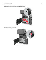 31
31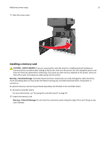 32
32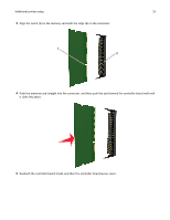 33
33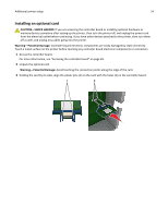 34
34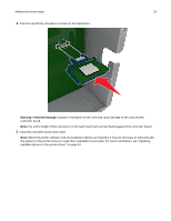 35
35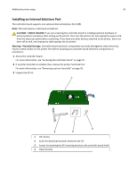 36
36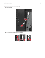 37
37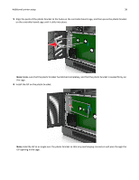 38
38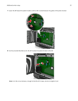 39
39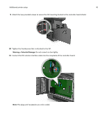 40
40 41
41

