Dell Force10 S55T Installing the S55 System - Page 11
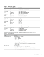
In addition to the system LEDs, each port has status indicator LEDs, described in, Table 2-1.
 |
View all Dell Force10 S55T manuals
Add to My Manuals
Save this manual to your list of manuals |
Page 11 highlights
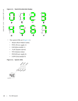
Table 2-1. System LED displays Label Master Power Supply (PSU1) Fan Module (FAN1) System alarms (ALM) System status (SYS) Power Supply (PSU0) Fan Module (FAN0) LED Color/Display Off Green solid Off Green solid Yellow solid Off Green solid Yellow solid Off Yellow solid Red solid Off Yellow solid Red solid Off Green solid Yellow solid Off Green solid Yellow solid Description Non-master unit, or stand-alone unit Stack master unit Power supply not present Power supply present and working Power supply present, but failed Fan tray not present Fan tray present and working Fan tray present, but failed No alarm Minor alarm Major alarm No alarm Minor alarm Major alarm Power supply not present Power supply present and working Power supply present, but failed Fan tray not present Fan tray present and working Fan tray present, but failed In addition to the system LEDs, each port has status indicator LEDs, described in Table 2-2. Table 2-2. Port LED Displays Feature 10/100/1000 Port LEDs SFP+ Port LED Description Link LED (left side of each port) Green - 1000M Yellow - 10/100M Off -No link Activity LED (right side of each port) Green - Link up on this port, full traffic Blinking Green - Activity, transmitting or receiving packet at this port. Off -No traffic Link/Activity LED Green - Link up on this port, no activity taking place Blinking Green - Activity, transmitting or receiving packet at this port. Off - No Link detected at this port The S55 System | 11
-
 1
1 -
2
-
3
-
4
-
5
-
 6
6 -
 7
7 -
 8
8 -
 9
9 -
 10
10 -
 11
11 -
 12
12 -
 13
13 -
 14
14 -
 15
15 -
 16
16 -
17
-
18
-
19
-
20
-
21
-
22
-
23
-
24
-
25
-
26
-
27
-
28
-
29
-
30
-
31
-
32
-
33
-
34
-
35
-
36
-
37
-
38
-
39
-
40
-
41
-
42
-
43
-
44
-
45
-
46
-
47
-
48
-
49
-
50
 |
 |