Dell Force10 S55T Installing the S55 System - Page 20
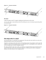
Insert optional modules
 |
View all Dell Force10 S55T manuals
Add to My Manuals
Save this manual to your list of manuals |
Page 20 highlights
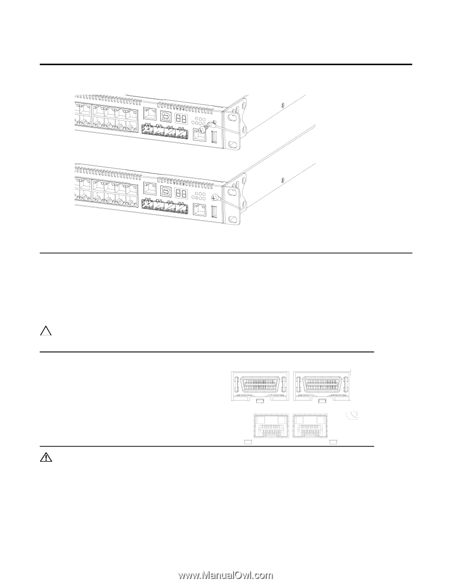
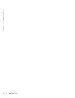
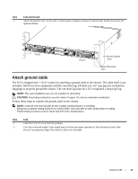
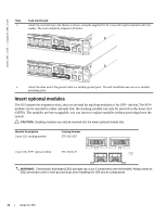
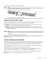
www.dell.com | support.dell.com Step Task (continued) 3 Attach the one-hole lug to the chassis as shown, using the supplied 10-32 screw with captive internal tooth lock washer. The screw should be torqued to 20 in-lbs. 4 Attach the other end of the ground cable to a suitable ground point. The rack installation ears are not a suitable grounding point. Insert optional modules The S55 system has expansion slots, that can be used for stacking modules or for SFP+ devices.The SFP+ module can be inserted in either optional slot; the stacking module can only be inserted in the lower slot (OPT0). The modules are hot-swappable; you can insert or replace modules without powering down the system. CAUTION: Stacking modules can only be inserted into the lower optional module slot. Module Description 2-port 12G stacking module Catalog Number S55-12G-2ST 2-port 10G SFP+ optical module S55-10GE-2S WARNING: Electrostatic discharge (ESD) damage can occur if components are mishandled. Always wear an ESD-preventive wrist or heel ground strap when handling the S55 and its components. 20 | Install the S55
-
 1
1 -
2
-
3
-
4
-
5
-
6
-
7
-
8
-
9
-
10
-
11
-
12
-
13
-
14
-
 15
15 -
 16
16 -
 17
17 -
 18
18 -
 19
19 -
 20
20 -
 21
21 -
 22
22 -
 23
23 -
 24
24 -
 25
25 -
26
-
27
-
28
-
29
-
30
-
31
-
32
-
33
-
34
-
35
-
36
-
37
-
38
-
39
-
40
-
41
-
42
-
43
-
44
-
45
-
46
-
47
-
48
-
49
-
50
 |
 |